
User Guide


Clamp-on Ground Resistance Tester Model 6416
27
6. MEASUREMENT MODES
6.1 Rotary Position W+A
6.1.1 Standard Mode
Selection of Standard mode is performed in the SET-UP (see § 4.4, menu #9).
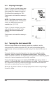
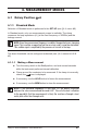
In Standard mode, only one measurement screen is available. The clamp
measures the loop impedance (W) (at the xed frequency of 2083Hz) and the
leakage current.
NOTE: Since the measurement frequency is audible, the operator hears a beeping
signal. This is neither an operating fault nor an alarm, and it cannot be eliminated.
This audible signal is amplified by the presence of current in the loop.
The alarm thresholds can be congured as desired (see § 4.4, menus #4, #5 &
#6).
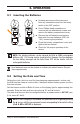
6.1.1.1 Making a Measurement
■ Turn the rotary switch to the Ω+A position, and wait several seconds
while the instrument performs internal calibration.
■ Clamp around the conductor to be measured. If the clamp is incorrectly
closed, the icon is displayed.
■ If necessary, use the HOLD button to freeze the measurement.
■ If necessary, use the MEM button to store the measurement.
NOTE: If the measured impedance is less than 1W, the display alternates
between the value measured and the word LOOP. This calls the user’s attention
to the possibility that the measurement is likely the resistance through a local
metal path rather than through earth.