
User Guide


28 Clamp-on Ground Resistance Tester Model 6416
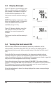
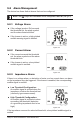
6.1.1.2 Measurement Results
Once the measurement has stabilized, the display
indicates:
- The leakage current.
- The impedance of the loop at the frequency of
2083Hz.
The impedance is measured only if the leakage
current is less than 10A. In the 10 to 40A range, only
the current is displayed; the NOISE symbol blinks
and the impedance is replaced by dashes.
To store the measurement into memory, press the MEM button (see § 5.7.2).
If the contact voltage exceeds 50V, the display indicates the current/impedance
measurements and the contact voltage alternately.
6.1.2 Advanced Mode
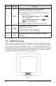
Selection of Advanced mode is performed in the SET-UP (see § 4.4, menu #9).
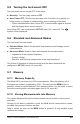
In this mode, three measurement screens are provided, impedance referred
to the chosen frequency and leakage current, contact voltage, display of R
(resistance) and L (inductance). The clamp measures the loop impedance
(W) at the frequency of 2083Hz. However, in addition to what is measured in
Standard mode, the impedance is recalculated at the frequency de ned by the
con guration.
The frequency and alarm thresholds can be con gured as desired (see § 4.4,
menus #4, #5 & #6).
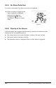
6.1.2.1 Making a Measurement
■ Turn the rotary switch to the Ω+A position, and wait several seconds
while the instrument performs internal calibration.
■ Clamp around the conductor to be measured. If the clamp is incorrectly
closed, the icon is displayed.
■ If necessary, use the HOLD button to freeze the measurement.
■ If necessary, use the MEM button to store the measurement.