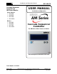
Installation and Operation Manual Cascade Sequencer Controller for AM Series Models: Water Heaters: • AM 399W • AM 500W • AM 750W • AM 1000W GF-146-CS USER MANUAL Installation and Operation 399 / 500 / 750 / 1000 Gas-Fired Boilers and Water Heaters Boilers: • AM 399B • AM 500B • AM 750B • AM 1000B Cascade Sequencer Controller For AM Series Water Heaters or Boilers Cascade Sequencer Controller Front Panel Latest Update: 11/25/2014 Page 1 of 26 PRI - 11/25/14 AERCO International, Inc.
AM Series Cascade Sequencer Installation and Operation Manual DISCLAIMER The information contained in this manual is subject to change without notice from AERCO International, Inc. AERCO makes no warranty of any kind with respect to this material, including, but not limited to, implied warranties of merchantability and fitness for a particular application.
AM Series Cascade Sequencer INSTALLATION AND OPERATION MANUAL TABLE OF CONTENTS INTRODUCTION .................................................................................................................. 4 CHAPTER 1: INSTALLATION ........................................................................................... 5 1.1 PIPING INSTALLATION .................................................................................................................... 5 1.2 ELECTRICAL INSTALLATION.............
AM Series Cascade Sequencer INSTALLATION AND OPERATION MANUAL INTRODUCTION The AM Series Cascade Sequencer controller is used to control a cascade arrangement of up to eight (8) AM Series water heaters or boilers. This document provides instructions for installation and operation of the cascade sequencer. Please note that the cascade sequencer requires a communications board be installed in each AM Series boiler or water heater.
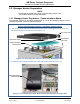
AM Series Cascade Sequencer INSTALLATION AND OPERATION MANUAL CHAPTER 1: INSTALLATION 1.1 Piping Installation WARNING! Prior to appliance installation and/or maintenance, disconnect the appliance’s electrical power supply and shut off the inlet gas valve. Failure to follow these instructions could result in severe personal injury or death! In order for the AM Cascade Sequencer to operate correctly, the AM Series heaters must be installed as shown in Figure 1-1.
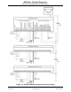
AM Series Cascade Sequencer INSTALLATION AND OPERATION MANUAL 1.2 Electrical Installation The electrical installation must be done as shown in Figure 1-2. Installer must install all wires represented by dashed lines. The “Cascade general sensor” is present inside each heater’s accessory box. This sensor must be electrically wired to terminals 24 and 25 of the Managing heater # 1 and placed into the low loss header of the cascade (see Figure 1-1).
AM Series Cascade Sequencer INSTALLATION AND OPERATION MANUAL Figure 1-2: Cascade Sequencing System Electrical Wiring OMM-0101_0A GF-146-CS AERCO International, Inc. • 100 Oritani Dr. • Blauvelt, NY 10913 Ph.
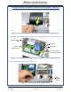
AM Series Cascade Sequencer INSTALLATION AND OPERATION MANUAL 1.3 Manager Heater Preparation NOTE Ensure that the heater being wired as the managing heater is the one installed closest to the low loss header. 1.3.1 Manager Heater Preparation - Communications Board To electrically prepare an AM Series heater/boiler for use as the Managing appliance for the Cascade Sequencer, follow the instructions below. Wiring the Manager Heater Communications Board 1.
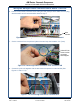
AM Series Cascade Sequencer INSTALLATION AND OPERATION MANUAL Wiring the Manager Heater Communications Board – Continued 3. Using a flat head screwdriver, open the communications board cover (see Figure 1-5). Figure 1-5: Using Screwdriver to Remove Communications Board Cover 4. Disconnect the 2-wire (pink/yellow) plug from the communications board (See Figure 1-6).
AM Series Cascade Sequencer INSTALLATION AND OPERATION MANUAL Wiring the Manager Heater communications Board – Continued 6. From the wire conduit, remove the two wires (pink and yellow) that are attached to the plug disconnected from the communications board in step 4. Wire Conduit Figure 1-8: Removing Pink and Yellow Wires from Wire Conduit 7. Cut the connector from the pink and yellow wires and strip the insulation 1/4” (7mm). Yellow & Pink wires cut from connector and stripped.
AM Series Cascade Sequencer INSTALLATION AND OPERATION MANUAL Wiring the Manager Heater Communications Board – Continued 9. Connect the yellow wire together with the two red wires present on terminal #17 (See Figures 1-11 and 1-12).
AM Series Cascade Sequencer INSTALLATION AND OPERATION MANUAL 1.3.2 Manager Heater Prep - S4 Switch on Communications Board The S4 switch on the communications board must be set to ON as described below. Setting Manager Heater Communications Board S4 Switch to ON 1. Locate the communications board at top of unit per previous wiring instructions. 2. Locate S4 switch at front edge of communications board per Figure 1-13. 3. Set S4 switch to ON (LEFT as you are facing the unit) per Figure 1-13.
AM Series Cascade Sequencer INSTALLATION AND OPERATION MANUAL 1.3.3 Manager Heater Preparation - S4 Switch on the Burner #1 Board The S4 switch on the Burner #1 (Master) board must be set to OFF as described below. Setting Manager Heater Burner #1 (Master) S4 Switch 1. Gain access to the Burner #1 (Master) Board and S4 switch by removing the front cover of managing unit. Note the location of the Burner #1 (Master) Board in Figure 1-14 (it is cyan colored in the image).
AM Series Cascade Sequencer INSTALLATION AND OPERATION MANUAL 1.4 Preparing the Cascade Sequencer for Use The Cascade Sequencer is used to program the logic address of each heater, as well as control the final cascade system, and must be wired as described below. Preparing the Cascade Sequencer for Use 1. Using a small flat head screwdriver, remove the rear cover of the Cascade Sequencer by levering up the panel via the slot, as shown in Figure 1-15.
AM Series Cascade Sequencer INSTALLATION AND OPERATION MANUAL Preparing the Cascade Sequencer for Use - Continued 3. Feed both wires through the rear panel conduit opening and snap rear panel onto rear of cascade Sequencer (Figure 1-17). Figure 1-17: Replacing Cascade Sequencer Rear Panel after Wiring 1.5 Setting the Logic Address for Each Heater Program the logic address of each heater using the Cascade Sequencer as described below. Setting the Logic Address for Each Heater NOTE Refer to Section 1.
AM Series Cascade Sequencer INSTALLATION AND OPERATION MANUAL Setting the Logic Address for Each Heater - Continued 3. Turn the power ON to the Managing heater #1. The Cascade Sequencer will also power up. 4. Wait until the Cascade Sequencer recognizes the boiler and “E2Prom Err” is not displayed. 5.
AM Series Cascade Sequencer INSTALLATION AND OPERATION MANUAL Setting the Logic Address for Each Heater - Continued 11. Repeat steps a) through g) in Step 5 setting the logic address to 2. 12. Turn the power OFF to the Dependent heater #2. 13. On the communications board at top of unit, set the S4 Switch (see Figure 1-13) to the OFF position. 14. Disconnect the two wires from terminals 16 and 17 of the Dependent heater #2. 15.
AM Series Cascade Sequencer INSTALLATION AND OPERATION MANUAL 1.7.1 AM Series Controller - Installer Menu Navigation This menu of parameters is available to qualified technicians for the purpose of analyzing the function of, and making adjustments to, the unit. Parameters for “Burner 1” are applicable for that burner only. To enter and make changes in the Installer Menu, perform the following steps: AM Series Controller - Installer Menu Navigation and Adjustment 1.
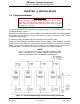
AM Series Cascade Sequencer INSTALLATION AND OPERATION MANUAL 1.8 Review of All Parameters Figure 1-18 diagrams a cascade setup using three (3) AM1000 units (with four burner boards in each unit). At the end of the installation process, all parameters (Address; Switch S4; 2003; 3001 and 3050) should have the values as shown on Figure 1-18.
AM Series Cascade Sequencer INSTALLATION AND OPERATION MANUAL CHAPTER 2: OPERATION NOTE After turning on power, wait at least 40 seconds for communication between sequencer and heaters to finish before performing any operations. Wait for the cascade manager to recognize the address of the master boiler or water heater. 2.1 Cascade Sequencer Display and Controls The AM Series Cascade Sequencer features a display and lower cover that is opened to reveal a number of buttons, as shown in Figure 2-1.
AM Series Cascade Sequencer INSTALLATION AND OPERATION MANUAL 2.2 Cascade Status Button By pressing the Cascade Status button (Figure 2-1), the lower half of the display will change to show the status of the cascade boilers (Figure 2-2). The designated number for each boiler in the cascade system will be displayed, such as 1, 2, 3, 4, etc., up to 8. If there is a request for heating for any heater, a flame icon will appear under that heater’s number.
AM Series Cascade Sequencer INSTALLATION AND OPERATION MANUAL Submenu Navigation and Parameter Settings – Continued 4. Use the Up or Down buttons to change the parameter value up or down. 5. When the desired value is displayed, save it by pressing the Ok button. To reject the change, do not press OK, and instead skip to the next step. 6. To leave the Sub Menu and return to the Main menu, press the Menu button (Figure 2-1).
AM Series Cascade Sequencer INSTALLATION AND OPERATION MANUAL 2.5 Sub-menu Parameter Range and Default settings Below is a list of the menu parameters with range and default settings. There is a table in the previous section that provides a description of each parameter.
AM Series Cascade Sequencer INSTALLATION AND OPERATION MANUAL 2.6 Troubleshooting Guide Below is a list of possible issues and corrective actions. Troubleshooting Guide Issue Corrective Action Cannot set the unit address when installing cascade sequencer OR When trying to set the unit address, the new address does not appear on the cascade sequencer. Cascade system does not seem to be communicating correctly. • Double check all wiring. • Ensure settings and switches are correct as per Figure 1-18.
AM Series Cascade Sequencer INSTALLATION AND OPERATION MANUAL NOTES: OMM-0101_0A GF-146-CS AERCO International, Inc. • 100 Oritani Dr. • Blauvelt, NY 10913 Ph.
AM Series Cascade Sequencer INSTALLATION AND OPERATION MANUAL Change Log: Date Description Changed By 11/25/2014 Rev-A: Released Curtis Harvey International, Inc. www.aerco.com Page 26 of 26 PRI - 11/25/14 AERCO International, Inc. • 100 Oritani Dr. • Blauvelt, NY 10913 Ph.