71150-00001.C I N S TA L L AT I O N A N D M A I N T E N A N C E I N S T R U C T I O N S F6/F7...
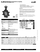
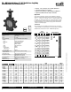
F6…HDU Butterfly Valves 2”–12” Ductile Iron Lug Body Resilient Seat, 304 Stainless Disc • 50 psi bubble tight shut-off • Long stem design allows for 2” insulation • Valve face-to-face dimensions comply with API 609 & MSS-SP-67 • Completely assembled and tested, ready for installation Application These valves are designed to meet the needs of HVAC and commercial applications requiring bubble tight shut-off for liquids.
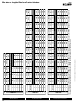
F6…HDU Butterfly Valves 2”–12” Ductile Iron Lug Body Resilient Seat, 304 Stainless Disc A 1.65 1.76 1.78 2.05 2.14 1.65 1.76 1.78 2.05 2.14 2.19 1.65 1.76 1.78 2.05 2.14 2.19 2.37 2.58 3.01 B 9.00 9.00 9.00 9.00 9.00 7.00 7.00 7.00 8.00 8.00 8.00 4.25 4.25 4.25 8.00 8.00 8.00 8.00 8.00 8.00 C 9.00 9.00 9.00 9.00 9.00 7.00 7.00 7.00 8.00 8.00 8.00 4.25 4.25 4.25 13.00 13.00 13.00 13.00 13.00 13.00 D(Max) 19.50 20.00 20.50 21.00 22.00 15.00 15.50 16.00 17.00 17.50 22.50 15.50 16.00 16.25 22.00 22.50 23.
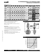
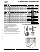
F7…HDU Butterfly Valves 2”–12” Ductile Iron Lug Body Resilient Seat, 304 Stainless Disc • 50 psi bubble tight shut-off • Long stem design allows for 2” insulation • Valve face-to-face dimensions comply with API 609 & MSS-SP-67 • Completely assembled and tested, ready for installation • Tees comply with ASME/ANSI B16.1 Class 125 flanges Application These valves are designed to meet the needs of HVAC and commercial applications requiring bubble tight shut off for liquids.
F7…HDU Butterfly Valves 2”–12” Ductile Iron Lug Body Resilient Seat, 304 Stainless Disc C 6.15 6.76 7.28 6.15 6.76 7.28 8.55 9.64 10.19 11.37 13.58 15.01 D(Max) 15.50 16.00 16.25 15.50 16.00 21.00 21.75 22.25 22.75 24.25 30.00 32.00 AF maximum actuator ambient temperature is 122°F. SY... maximum actuator ambient temperature is 150°F. Model SY1… does not have hand wheel-override is via 8mm wrench on bottom side of actuator. BHC 4.75 5.50 6.00 4.75 5.50 6.00 7.50 8.50 9.50 11.75 14.25 17.00 No.
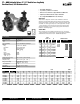
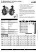
F6…HD Butterfly Valves 2”–30” Ductile Iron Lug Body Resilient Seat, 304 Stainless Disc • 200 psi (2” to 12”) and 150 psi (14”-30”) bubble tight shut-off • Long stem design allows for 2” insulation • Valve face-to-face dimensions comply with API 609 & MSS-SP-67 • Completely assembled and tested, ready for installation Application These valves are designed to meet the needs of HVAC and commercial applications requiring bubble tight shut-off for liquids.
F6…HD Butterfly Valves 2”–30” Ductile Iron Lug Body Resilient Seat, 304 Stainless Disc Cv 60° 44 A 1.65 B 9.00 C 9.00 D(Max) 19.50 BHC 4.75 No. of Holes 4 Lug Bolt 5/8-11UNC Actuator AF 2½” 196 75 1.76 9.00 9.00 20.00 5.50 4 5/8-11UNC F680HD 3” 302 116 1.78 9.00 9.00 20.50 6.00 4 5/8-11UNC F650HD 2” 115 44 1.65 7.00 7.00 15.00 4.75 4 5/8-11UNC F665HD 2½” 196 75 1.76 7.00 7.00 15.50 5.50 4 5/8-11UNC F680HD 3” 302 116 1.78 8.00 8.00 16.00 6.
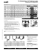
F7…HD Butterfly Valves 2”–24” Ductile Iron Lug Body Resilient Seat, 304 Stainless Disc • 200 psi (2” to 12”) and 150 psi (14”-30”) bubble tight shut-off • Long stem design allows for 2” insulation • Valve face-to-face dimensions comply with API 609 & MSS-SP-67 • Completely assembled and tested, ready for installation • Tees comply with ASME/ANSI B16.1 Class 125 flanges Application These valves are designed to meet the needs of HVAC and commercial applications requiring bubble tight shut off for liquids.
F7…HD Butterfly Valves 2”–24” Ductile Iron Lug Body Resilient Seat, 304 Stainless Disc C D(Max) BHC No. of Holes Lug Bolt Actuator 115 4.50 6.15 6.15 20.25 4.75 4 5/8-11UNC AF F765HD 2½” 196 5.00 6.76 6.76 20.75 5.50 4 5/8-11UNC 2*AF F750HD F765HD F780HD F7100HD F7125HD F7150HD F7200HD F7250HD F7300HD F7350HD F7400HD F7450HD F7500HD F7600HD 2” 2½” 3” 4” 5” 6” 8” 10” 12” 14” 16” 18” 20” 24” 115 196 302 600 1022 1579 3136 5340 8250 11917 16388 21705 27908 43116 4.50 5.00 5.50 6.
24 VAC 110 VAC 800-543-9038 USA 866-805-7089 CANADA 203-791-8396 LATIN AMERICA SY2 Amps 357 606 905 SY1 Amps 12 10 8 Amps 5882 10000 14925 SY1 Amps 12 10 8 5051 7937 12821 19608 33333 49751 18 16 14 12 10 8 0.3 SY2 3846 14 wire gauge 7463 2381 29851 20000 11765 7692 4762 3030 0.5 5000 2941 1923 1190 1515 16 758 1 364 214 140 18 0.5 543 233 14 87 144 16 55 92 wire gauge 3 Amps SY3 6 Amps SY4 6.
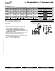
Interface Wiring Detail SYx-MFT, 24V, 120/230V Actuators: SYx-MFT Notes: INSTALLATION NOTES 1. Motor CAMS have been factory calibrated and should not be moved. 2. An adaption must be performed if any limit switch is adjusted. This will calibrate the beginning and end stopping points. Press the adaption button for 3 seconds and release.
SYx-P Interface Wiring Detail Open LED Closed LED N Supply H - SIG + IN Sensitivity Sensitivity switchsetting is position #3 for factory default. To T widen deadband, select a higher number (up to 9). VR2 - FB + OUT VR1 Dip Switch INSTALLATION NOTES CAUTION Dip Switch Settings Notes: 1. Applicable to the SY1 and legacy SY2-12 actuators. 2. Do not change sensitivity or dip switch settings with power applied! 3. VR1 and VR2 are factory calibrated and should not be moved. 4.
SY… Series Non-Spring Actuators CAUTION Electrical Travel Adjustment (Factory Pre-set) SY-1 Factory pre-set see chart below. Field adjustable if required LS4 Auxiliary Switch for Closed Indication LS3 Auxiliary Switch for Opened Indication LS4 LS3 LS2 LS1 Factory pre-set and calibrated.
Wiring for Damper Actuators and Control Valves On/Off, 24V, 120/230V SY1-110 SY2...12-110 SY2...12-220 W546 Actuators: SY1-24 Hazard Identification INSTALLATION NOTES Warnings and Cautions appear at appropriate sections throughout this manual. Read these carefully. Observe class 1 and class 2 wiring restrictions. CAUTION Indicates a potentially hazardous situation which, if not avoided, may result in minor or moderate injury. It may also be used to alert against unsafe practices.
Wiring for Damper Actuators and Control Valves Proportional, 24V, 120/230V W547 Actuators: SY1-24P SY1-110P SY1-220P Hazard Identification INSTALLATION NOTES 7ARNINGS AND #AUTIONS APPEAR AT APPROPRIATE SECTIONS THROUGHOUT this manual. Read these carefully.
Wiring for Damper Actuators and Control Valves Proportional, 24V, 120/230V SY2...5-24MFT SY2...12-120MFT SY2...12-230MFT Hazard Identification W547-2 Actuators: INSTALLATION NOTES 7ARNINGS AND #AUTIONS APPEAR AT APPROPRIATE SECTIONS THROUGHOUT this manual. Read these carefully.
Wiring for Damper Actuators and Control Valves On/Off, 24V, 110/120/230V Actuators: SY1...5-24 SY1...12-110 SY1...12-220 Hazard Identification INSTALLATION NOTES Warnings and Cautions appear at appropriate sections throughout this manual. Read these carefully. Observe class 1 and class 2 wiring restrictions. CAUTION Indicates a potentially hazardous situation which, if not avoided, may result in minor or moderate injury. It may also be used to alert against unsafe practices.
Wiring for Control Valves Proportional, 24V W550 Actuators: SY1-24P Hazard Identification 33 Warnings and Cautions appear at appropriate sections throughout this manual. Read these carefully. 24 VAC Transformer G Line Volts CAUTION Indicates a potentially hazardous situation which, if not avoided, may result in minor or moderate injury. It may also be used to alert against unsafe practices.
Wiring for Control Valves Proportional, Multiple Wiring, 24V W550-2 Actuators: SY2...5-24MFT Hazard Identification INSTALLATION NOTES Warnings and Cautions appear at appropriate sections throughout this manual. Read these carefully. Observe class 1 and class 2 wiring restrictions. CAUTION Transformer sizing = SY actuator draw X 1.25 (safety margin) (Ex. SY2-24 requires 3.0A x 1.25 = 3.75A, 3.75A X 24 VAC = 90VA Transformer).
Wiring for Control Valves Proportional, 110/220V, 120/230V SY1-220P W552-1 Actuators: SY1-110P G Actuator B G Ground N L1 4 Power Supply Com H L2 5 Power Supply Hot CAUTION 6 Control Signal (-) Indicates a potentially hazardous situation which, if not avoided, may result in minor or moderate injury. It may also be used to alert against unsafe practices.
Wiring for Control Valves Proportional, Multiple Wiring, 120/230V SY2...12-230MFT W552-2 Actuators: SY2...12-120MFT Hazard Identification INSTALLATION NOTES Warnings and Cautions appear at appropriate sections throughout this manual. Read these carefully. Observe class 1 and class 2 wiring restrictions. CAUTION Indicates a potentially hazardous situation which, if not avoided, may result in minor or moderate injury. It may also be used to alert against unsafe practices.
AF Actuators, On/Off BF2WUDIM_A Dimensions with 2-Way Valve D B C A BHC AF24 US AF24-S US w/built-in Aux. Switches AF120 US AF120-S US w/built-in Aux. Switches Technical Data Control Power consumption AF24(-S) US AF120(-S) US Transformer sizing Electrical connection Electrical protection Overload protection Angle of rotation Position indication Manual override Running time Ambient temperature Housing Agency listings Noise level AF...
AF Actuators, On/Off B Line Volts 1 Common 2 + Hot AF24 US 10 D 24 VAC Transformer HS DWGP11 A j y W194 p Dimensions with 3-Way Valve 3 2 On/Off Wiring W195-AUX C 10 Valve Size F750HD 2” F750HDU 2” F765HD 2½” F765HDU 2½” F780HDU 3” A 4.50 4.50 5.00 5.00 5.50 Dimensions (Inches) B C D(Max) 6.15 6.15 15.50 6.15 6.15 15.50 6.76 6.76 16.00 6.76 6.76 16.00 7.28 7.28 16.25 BHC 4.75 4.75 5.50 5.50 6.
AF Actuators, Multi-Function Technology BF2WUDIM BF2WUDIM_A Dimensions with 2-Way Valve D Models C B w/built-in Aux. Switches Technical Data † Rated Impulse Voltage 800V, Type of action 1.AA (1.AA.B for -S version), Control Pollution Degree 3. Programmed for 70 sec motor run time. At 150 sec motor run time, transformer sizing iis 8.5 VA and power consumption is 6 W running / 3 W holding. Size 2” 2” 2½” 2½” 3” 3” 4” 5” 2” 2½” 3” 4” 2” 2½” 3” 4” Dimensions (Inches) B C D(Max) 9.00 9.00 19.50 9.
AF Actuators, Multi-Function Technology W399_Butterfly Wiring Diagrams 3 Actuators may also be powered by 24 VDC. 4 IN4004 or IN4007 diode (IN4007 supplied, Belimo part number 40155). 5 Triac A and B can also be contact closures. Control signal may be pulsed from either the Hot (Source) or Common (Sink) 24 VAC line. Position feedback cannot be used with Triac sink controller. The actuators internal common reference is not compatible.
GKB24-3-X1 Actuators, On/Off, Floating Point AM_GM_LineRevised Dimensions with 2-Way Valve D B C A BHC Non-Fail Safe (psi) GK 200 50 50 285 285 285 150 285 Dimensions (Inches) Overload protection Operation range Y Input impedance Feedback output U Angle of rotation Direction of rotation Fail-safe position 26 B 7.00 8.00 8.00 9.00 9.00 9.00 9.00 9.00 C D(Max) BHC 7.00 16.53 6.00 8.00 17.53 7.50 8.00 18.03 8.50 9.00 20.03 4.75 9.00 20.53 5.50 9.00 21.03 6.00 9.00 21.53 7.50 9.00 20.03 5.
GKB24-3-X1 Actuators, On/Off, Floating Point Wiring Diagrams Electrical Installation T – ~ Wiring diagram + Note ! • Connect via safety isolation transformer. • Parallel connection of other actuators possible. Note performance data for supply. DC 0 ... 10 V Y U 1 2 3 1 Provide overload protection and disconnect as required. 3 Actuators may also be powered by 24 VDC. DC 2 ...
GKX24-MFT-X1 Actuators, Multi-Function Technology AM_GM_LineRevised Dimensions with 2-Way Valve D B C A BHC Power consumption Transformer sizing Electrical connection Overload protection Operation range Y Input impedance Feedback output U Angle of rotation Direction of rotation Fail-safe position A 1.69 1.92 2.08 1.75 1.88 1.92 2.13 1.75 B 9.00 9.00 9.00 9.00 9.00 9.00 9.00 9.00 C D(Max) BHC 9.00 21.03 6.00 9.00 21.53 7.50 9.00 22.53 8.50 9.00 20.03 4.75 9.00 20.53 5.50 9.00 21.03 6.00 9.00 21.
GKX24-MFT-X1 Actuators, Multi-Function Technology Provide overload protection and disconnect as required. 3 Actuators may also be powered by 24 VDC. 4 5 8 9 Position feedback cannot be used with Triac sink controller. The actuator internal common reference is not compatible. Control signal may be pulsed from either the Hot (source) or the Common (sink) 24 VAC line. Contact closures A & B also can be triacs. A & B should both be closed for triac source and open for triac sink.
AM Series Actuators, On/Off, Floating Point AM_GM_LineRevised Dimensions with 2-Way Valve D B C A BHC Non-Fail Safe (psi) HD HDU 200 50 200 50 50 Dimensions (Inches) Valve Size F650HD(U) 2” F665HD(U) 2½” F680HDU 3” Technical Data Power supply Power consumption Transformer sizing Electrical connection 800-543-9038 USA 30 C 7.00 7.00 7.00 D(Max) 15.00 15.50 16.00 BHC 4.75 5.50 6.00 Dimensions with 3-Way Valve A B D 0 Noise level Quality standard B 7.00 7.00 7.
j y Wiring Diagrams 24 VAC Transformer 4 Actuators may be connected in parallel. Power consumption and input impedance must be observed. 5 Blk (1) Common Line Volts CAUTION Equipment damage! 3 Red (2) + a a open a closed Actuators may also be powered by 24 VDC. Wht (3) + 1 0 The indication of direction is valid for switch position 1. Meets cULus or UL and CSA requirements without the need of an electrical ground connection.
AM Series Actuators, Multi-Function Technology AM_GM_LineRevised Dimensions with 2-Way Valve D B C A BHC Models A 1.65 1.76 1.78 Dimensions (Inches) B C D(Max) 7.00 7.00 15.00 7.00 7.00 15.50 7.00 7.00 16 .00 BHC 4.75 5.50 6.00 Non-Fail Safe (psi) Valve Size F650HD(U) 2” F665HD(U) 2½” F680HDU 3” AMX24-MFT-X1 A B Dimensions (Inches) Valve F750HD F765HDU Size 2” 2½” A 4.50 5.00 B 6.15 6.76 C 6.15 6.76 D(Max) 15.50 16.00 BHC 4.75 5.
AM Series Actuators, Multi-Function Technology 24 VAC/DC Transformer 4 6 8 9 3 Blk (1) Common Line Volts Actuators may also be powered by 24 VDC. Position feedback cannot be used with Triac sink controller. The actuator internal common reference is not compatible. Control signal may be pulsed from either the Hot (source) or the Common (sink) 24 VAC line. Contact closures A & B also can be triacs. A& B should both be closed for triac source and open for triac sink.
GMB24-3-X1 Actuators, On/Off, Floating Point AM_GM_LineRevised Dimensions with 2-Way Valve D B C A BHC Dimensions (Inches) GMB24-3-X1 Technical Data Power supply Power consumption Transformer sizing Electrical connection Overload protection Control signal Input impedance Angle of rotation Direction of rotation Position indication Running time Humidity Ambient temperature Storage temperature Housing Housing material Agency listings Noise level Servicing Quality standard 24 VAC ± 20% 50/60 Hz 24 VDC
GMB24-3-X1 Actuators, On/Off, Floating Point Dimensions with 3-Way Valve D101 Wiring Diagrams B CAUTION Equipment damage! 2 C 0 10 Dimensions (Inches) C D(Max) BHC 6.70 16.00 5.50 7.20 16.25 6.00 7.20 16.25 6.00 8.45 17.00 7.50 Non-Fail Safe (psi) GM 2*GM 200 200 50 200 Valve F765HD F780HD F780HDU F7100HD Size 2½” 3” 3” 4” A 5.00 5.50 5.50 6.50 B 6.70 7.20 7.20 8.45 F7100HDU F7125HDU F7150HDU F750-150SHP F765-150SHP 4” 5” 6” 2” 2½” 6.50 7.50 8.00 4.50 5.00 8.45 8.45 9.60 9.60 10.08 10.08 6.
GMX24-MFT-X1 Actuators, Multi-Function Technology AM_GM_LineRevised Dimensions with 2-Way Valve D B C A BHC Dimensions (Inches) Technical Data Power supply 24 VAC ± 20% 50/60 Hz Power consumption Transformer sizing Electrical connection Overload protection Control signal Input impedance C D(Max) BHC 9.00 20.50 6.00 9.00 21.00 7.50 9.00 21.00 7.50 9.00 22.00 8.50 9.00 22.50 9.50 9.00 19.50 4.75 9.00 20.00 5.50 9.00 20.50 6.00 9.00 21.00 7.50 F650-300SHP 2” 1.75 9.00 9.00 19.50 5.
GMX24-MFT-X1 Actuators, Multi-Function Technology 3 24 VAC Transformer 3 5 8 10 Red (2) + Hot Ω Actuators with plenum rated cable do not have numbers on wires; use color coded instead. Actuators with appliance rated cable use numbers. Control signal may be pulsed from either the Hot (Source) or Common (Sink) 24 VAC line. For triac sink the Common connection from the actuator must be connected to the Hot connection of the controller.
Installation Recommendations F6…HD(U), F7…HD(U) Series Butterfly Valves HD(U) Series Butterfly Valves Storage of Butterfly Valve Assemblies Installation using Welded Flanges ● Assemblies must be stored indoors, protected from the elements. ● Materials received on job sites that have long installation lead times should receive extra protection from construction damage. ● Resilient seats must be protected from abrasion, cutting and nicking, as this will damage the liner and may cause flange area leaks.
Installation Recommendations F6…HD(U), F7…HD(U) Series Butterfly Valves HD(U) Series Butterfly Valves 1Fig. 1 Fig. 1 3a 2 1 15 ... 20° Fig. 1 3b Fig. 1a 800-543-9038 USA 0 1Fig. 2 >0 07/10 - Subject to change. © Belimo Aircontrols (USA), Inc. 1Fig.
Installation Recommendations F6…HD(U), F7…HD(U) Series Butterfly Valves FLANGE BOLTING RECOMMENDATIONS Flange Detail for ANSI B16.
Installation Recommendations F6...HD(U), F7...HD(U) Series Butterfly Valves Fig. 6 Valve Installation Procedure Position the connecting pipe flanges in the line to insure proper alignment prior to valve installation. Spread the pipe flanges apart enough to allow the valve body to be located between the flanges without actually contacting the flange surfaces. Exercise particular care in handling the valve so as to prevent possible damage to the disc or seat faces.
01/10 - Subject to change. © Belimo Aircontrols (USA), Inc.
Installation Recommendations F6…HD(U), F7…HD(U) Series Butterfly Valves 1Fig. 9 Valve Installation- Dead End Service 1. Follow previously described pre-installation and installation procedures. 2. To achieve the full close-off pressure of the HD/HDU series, a flange is required on the open or down stream side of the valve (Fig. 9) Maintenance Instructions Safety Precautions Before removing the valve from the line or loosening any bolts, it is important to verify the following conditions: 1.
Subject to change. © Belimo Aircontrols (USA), Inc. Belimo worldwide: www.belimo.com BELIMO Americas USA Locations, 43 Old Ridgebury Road, Danbury, CT 06810 Tel. 800-543-9038, Fax 800-228-8283, marketing@us.belimo.com 1049 Fortunado Loop, Sparks, NV 89436 Tel. 800-987-9042, Fax 800-987-8875, marketing@us.belimo.com Canada Locations, 14/16 – 5716 Coopers Avenue, Mississauga, Ontario L4Z 2E8 Tel. 866-805-7089, Fax 905-712-3124, marketing@us.belimo.com Latin America and The Caribbean Customer Service Tel.