
Manual


800-543-9038 USA 866-805-7089 CANADA 203-791-8396 LATIN AMERICA
38
0
7/10 - Subject to change. © Belimo Aircontrols (USA), Inc.
S
torage of Butterfly Valve Assemblie
s
● Assemblies must be stored indoors, protected from the elements.
●
Materials received on job sites that have long installation lead
times should receive extra protection from construction damage.
●
Resilient seats must be protected from abrasion, cuttin
g
and nick
-
ing, as this will damage the liner and may cause flange area leaks.
● Electric actuators cannot be stored in wet, damp or caustic areas
.
●
Do not store construction material on top of valve assemblies
.
Installati
o
n Practice
s
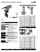
●
HD(U) series butterfly valves are designed to be installed between
ANSI 125/150 flat-faced, raised face, slip-on or weld neck flanges.
●
Valve should be installed a minimum of 10
p
i
p
e diameters
from upstream or downstream elbows, strainers, pumps, etc
.
●
F
or c
hill
e
d
water, con
d
enser water or
h
ot water app
li
cat
i
ons, t
h
e
va
l
ve s
h
ou
ld
b
e
i
nsta
ll
e
d
w
i
t
h
t
h
e stem
i
n a vert
i
ca
l
or
i
entat
i
on
,
w
ith the actuator mounted above the valve
.
●
For applications in which there is a possibility of sediment in the
flow
,
the valve should be installed with the stem in a horizontal
position and the bottom of the disc should close FR
O
M the down-
s
tream side, rather than from the u
p
stream side.
●
Make sure the flange faces are clean and free of rust, scale and
debris to prevent damage to the liner face.
●
Do NOT use flange gaskets on HD
(
U
)
series BF valves.
(
Fig. 1a
)
● Follow the recommended flange bolting sequence.
(
Fig. 8, pg. 85
)
●
Wh
en
i
nsta
lli
ng
i
n
Vi
ctau
li
c p
i
p
i
ng systems, use
Vi
ctau
li
c
41
ser
i
es
flange nipples.
I
nsta
ll
at
i
on us
i
ng
W
e
ld
e
d
Fl
ange
s
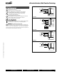
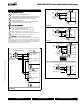
● Mount flanges on both sides of valve body and install bolts to
p
roperly align valve body and both flanges.
● Install the valve with the disc in the “Almost Closed” position (Fig. 1
)
●
Do not use any flange gaskets (Fig. 1a)
● Make sure the valve liner and flange internal diameters are in
alignment. (Fig. 2)
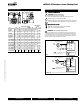
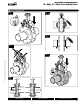
●
T
ake valve bod
y
/ flange pair assembl
y
and align with piping ends
.
●
T
ACK weld the flanges to the piping in several places. (Fig. 3a)
D
o N
O
T seam weld at this time
!
●
Remove the lug bolts and carefull
y
remove the valve bod
y
from
t
he flan
g
es.
●
S
eam weld the entire flan
g
e / pipin
g
connection for both flan
g
es.
(Fig 3b
)
●
L
et the piping components cool completely be
f
ore re-inserting the
v
alve body. (Fig. 4)
●
WARNING!
Seam welding with the valve body installed between
!
t
he
f
langes can damage the liner due to heat migration through
t
he
f
lange to the valve bod
y
.
I
n
s
t
alla
t
io
n
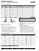
Reco
mm
e
n
da
t
io
n
s
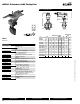
F6…HD
(
U
)
, F7…HD
(
U
)
S
eries Butter
fl
y Valve
s
HD(U) Series Butterfl y Valves