
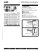
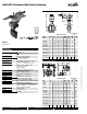
Manual


800-543-9038 USA 866-805-7089 CANADA 203-791-8396 LATIN AMERICA
41
0
7/10 - Subject to change. © Belimo Aircontrols
(
USA
)
, Inc
.
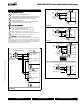
Valve Installation Procedur
e
P
osition the connectin
g
pipe
fl
an
g
es in the line to insure proper
a
lignment prior to valve installation. Spread the pipe fl anges apart
e
nough to allow the valve body to be located between the
fl
anges
w
ithout actually contacting the
fl
ange sur
f
aces. Exercise particular
care in handling the valve so as to prevent possible damage to the disc
or seat
f
aces.
N
o
te: Actuator must be mounted at or above pipe center line for all
actuator types.
(
Fig. 6
)
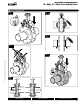
1. For Lug st
y
le valves:
a
. Place the valve between the
fl
anges
.
b. Install all bolts between the valve and the mating
fl
anges.
Hand tighten bolts as necessary. (Fig. 7
)
2. Be
f
ore completing the tightening o
f
any bolts, the valve should be
centered between the
fl
anges and then care
f
ully opened and closed
to insure
f
ree, unobstructed disc movement.
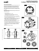
3. Using the sequence,
(
Fig. 8
)
tighten the
fl
ange bolts evenly to assure
u
ni
f
orm compression. In assembling
fl
ange joints, the resilient
seating sur
f
ace shall be uni
f
ormly compressed.
(
Fig. 5
)
4
. I
f
an actuator is to be operated, electricity should be connected to
the unit in accordance with the local electrical code
s
.
5
. C
y
cle the valve to the full
y
open position, then back to the full
y
closed position, checking the actuator travel stop settings
f
or proper
d
isc alignment. The valve should be operated to assure that no
bindin
g
is takin
g
place. I
f
no power is available, use the manual
h
an
d
w
h
ee
l
.
6
. The valve is now read
y
f
or operation.
1
1
Fig. 7
In
s
t
a
ll
a
ti
o
n R
eco
mm
e
n
da
ti
o
n
s
F6...HD
(
U
)
, F7...HD
(
U
)
S
eries Butter
fl
y Valve
s
Fig. 5
>
0
0
0
>
0
Fig. 6
90° 90°
1
1
Fig. 8
31
24
1
4
3
2
5
6
7
8
9
10
11
12
13
14
15
16
1
4
3
2
5
6
7
8
9
10
11
12
1
4
3
2
5
6
7
8