Benchmark 1.5LN Low NOx Boiler GF-120 Installation, Operation and Maintenance Manual Modulating, Condensing, Forced Draft, Hot Water Boiler 1,500,000 BTU/H Input Applicable for Serial Numbers: G-12-1953 and above. OMM-0041_0E Benchmark 1.5LN Low NOx Boiler USER MANUAL Installation, Operation, and Maintenance Benchmark 1.5LN Low NOx Boiler Revised: 10/18/2012 PR1: 10/18//12 AERCO International Inc. • 100 Oritani Dr.
GF-120 OMM-0041 0E Benchmark 1.5LN Low NOx Boiler Installation, Operation and Maintenance Manual Technical Support: (Mon–Fri, 8am-5pm EST) 1-800-526-0288 www.aerco.com Disclaimer The information contained in this manual is subject to change without notice from AERCO International, Inc. AERCO makes no warranty of any kind with respect to this material, including but not limited to implied warranties of merchantability and fitness for a particular application.
Benchmark 1.5LN Low NOx Boiler Installation, Operation and Maintenance Manual GF-120 OMM-0041_0E Table of Contents CHAPTER 1. SAFETY PRECAUTIONS ............................................................................... 9 1.1 WARNINGS & CAUTIONS ..................................................................................................................... 9 1.2 EMERGENCY SHUTDOWN .................................................................................................................
GF-120 OMM-0041 0E Benchmark 1.5LN Low NOx Boiler Installation, Operation and Maintenance Manual 2.12 FLUE GAS VENT INSTALLATION ..................................................................................................... 27 2.13 COMBUSTION AIR ............................................................................................................................. 28 2.13.1 Combustion Air From Outside the Building ...............................................................................
Benchmark 1.5LN Low NOx Boiler Installation, Operation and Maintenance Manual GF-120 OMM-0041_0E 5.5 DIRECT DRIVE MODES....................................................................................................................... 64 5.5.1 Direct Drive Field Wiring ................................................................................................................ 65 5.5.2 Direct Drive Startup .............................................................................................
GF-120 OMM-0041 0E CHAPTER 9. Benchmark 1.5LN Low NOx Boiler Installation, Operation and Maintenance Manual RS232 COMMUNICATION ..........................................................................105 9.1 INTRODUCTION................................................................................................................................. 105 9.1.1 Aquiring the PuTTY Application ................................................................................................... 105 9.1.
GF-120 OMM-0041 0E Benchmark 1.5LN Low NOx Boiler Installation, Operation and Maintenance Manual Foreword Foreword The AERCO Benchmark 1.5LN Boiler is a modulating unit. It represents a true industry advance that meets the needs of today's energy and environmental concerns. Designed for application in any closed loop hydronic system, the Benchmark's modulating capability relates energy input directly to fluctuating system loads. The Benchmark 1.
GF-120 OMM-0041 0E Benchmark 1.5LN Low NOx Boiler Installation, Operation and Maintenance Manual (This page left intentionally blank) Page 8 of 166 AERCO International Inc. • 100 Oritani Dr.
GF-120 Benchmark 1.5LN Low NOx Boiler OMM-0041 0E Installation, Operation and Maintenance Manual CHAPTER 1 SAFETY PRECAUTIONS CHAPTER 1. SAFETY PRECAUTIONS 1.1 WARNINGS & CAUTIONS Installers and operating personnel MUST, at all times, observe all safety regulations. The following warnings and cautions are general and must be given the same attention as specific precautions included in these instructions.
CHAPTER 1 SAFETY PRECAUTIONS Benchmark 1.5LN Low NOx Boiler Installation, Operation and Maintenance Manual GF-120 OMM-0041 0E WARNING ELECTRICAL VOLTAGES UP TO 120 VAC MAY BE USED IN THIS EQUIPMENT. THEREFORE THE COVER ON THE UNIT’S POWER BOX (LOCATED BEHIND THE FRONT PANEL DOOR) MUST BE INSTALLED AT ALL TIMES, EXCEPT DURING MAINTENANCE AND SERVICING. CAUTIONS Must be observed to prevent equipment damage or loss of operating effectiveness.
GF-120 Benchmark 1.5LN Low NOx Boiler OMM-0041 0E Installation, Operation and Maintenance Manual • • • • • CHAPTER 1 SAFETY PRECAUTIONS IMPORTANT – FOR MASSACHUSETTS INSTALLATIONS ONLY Boiler Installations within the Commonwealth of Massachusetts must conform to the following requirements: Boiler must be installed by a plumber or a gas fitter who is licensed within the Commonwealth of Massachusetts.
CHAPTER 1 SAFETY PRECAUTIONS Benchmark 1.5LN Low NOx Boiler Installation, Operation and Maintenance Manual GF-120 OMM-0041 0E "GAS VENT DIRECTLY BELOW. KEEP CLEAR OF ALL OBSTRUCTIONS". 4. INSPECTION. The state or local gas inspector of the side wall horizontally vented gas fueled equipment shall not approve the installation unless, upon inspection, the inspector observes carbon monoxide detectors and signage installed in accordance with the provisions of 248 CMR 5.08(2)(a)1 through 4.
GF-120 Benchmark 1.5LN Low NOx Boiler OMM-0041 0E Installation, Operation and Maintenance Manual CHAPTER 2 INSTALLATION CHAPTER 2. INSTALLATION 2.1 INTRODUCTION This Chapter provides the descriptions and procedures necessary to unpack, inspect and install the AERCO Benchmark 1.5 Boiler. Brief descriptions are also provided for each available mode of operation. Detailed procedures for implementing these modes are provided in Chapter 5. 2.2 RECEIVING THE UNIT Each Benchmark 1.
CHAPTER 2 INSTALLATION Benchmark 1.5LN Low NOx Boiler GF-120 Installation, Operation and Maintenance Manual OMM-0041 0E 2.4 SITE PREPARATION. Ensure that the site selected for installation of the Benchmark 1.5 Boiler includes: • Access to AC Input Power at 120 VAC, 1-Phase, 60 Hz @ 20 • Access to Natural Gas line at a minimum pressure of 4 inches W.C. 2.4.1 Installation Clearances The unit must be installed with the prescribed clearances for service as shown in Figure 2-1.
GF-120 Benchmark 1.5LN Low NOx Boiler OMM-0041 0E Installation, Operation and Maintenance Manual CHAPTER 2 INSTALLATION 2.4.2 Setting the Unit The unit must be installed on a 4 inch to 6 inch housekeeping pad (see NOTE below) to ensure proper condensate drainage. If anchoring the unit, refer to the dimensional drawings in Appendix F for anchor locations. Two lifting tabs are provided at the top of the heat exchanger. Figure 2-2 shows the location of the tab on the top-left side.
CHAPTER 2 INSTALLATION Benchmark 1.5LN Low NOx Boiler GF-120 Installation, Operation and Maintenance Manual OMM-0041 0E If installing a Combination Control Panel (CCP) system, it is important to identify the Combination Mode Boilers in advance and place them in the proper physical location. Refer to Chapter 5 for information on Combination Mode Boilers. 2.5 SUPPLY AND RETURN PIPING The Benchmark 1.5 Boiler utilizes 3” 150# flanges for the water system supply and return piping connections.
GF-120 Benchmark 1.5LN Low NOx Boiler OMM-0041 0E Installation, Operation and Maintenance Manual CHAPTER 2 INSTALLATION EXHAUST MANIFOLD BOILER RETURN CONDENSATE DRAIN CONNECTION PARTIAL REAR VIEW Figure 2-4: Condensate Drain Connection Location 2.6.1 Exhaust Manifold Condensate Drain The exhaust manifold drain pipe connection shown in Figure 2-4, must be connected to a condensate drain trap external to the unit.
CHAPTER 2 INSTALLATION Benchmark 1.5LN Low NOx Boiler GF-120 Installation, Operation and Maintenance Manual OMM-0041 0E Figure 2-5: Condensate Trap Installation: Older (left) and Newer (right) Style 2.7 GAS SUPPLY PIPING The AERCO Benchmark 1.5 Gas Components and Supply Design Guide, GF-4030 must be consulted prior to designing or installing any gas supply piping. WARNING NEVER USE MATCHES, CANDLES, FLAMES OR OTHER SOURCES OF IGNITION TO CHECK FOR GAS LEAKS.
GF-120 Benchmark 1.5LN Low NOx Boiler OMM-0041 0E Installation, Operation and Maintenance Manual CHAPTER 2 INSTALLATION 2.7.1 Gas Supply Specifications. The gas supply input specifications to the unit for Natural Gas are as follows: • The maximum static pressure to the unit must not exceed 14” W.C. • The gas supply pressure to the unit must be of sufficient capacity to provide 1500 cfh while maintaining the gas pressure at 4.0 inches W.C. for FM, or 4.2 inches W.C. for IRI gas trains. 2.7.
CHAPTER 2 INSTALLATION Benchmark 1.5LN Low NOx Boiler GF-120 Installation, Operation and Maintenance Manual OMM-0041 0E NATURAL GAS SUPPLY 1-1/2” MANUAL GAS SHUTOFF VALVE GAS PRESSURE REGULATOR (REQUIRED FOR MASSACHUSETTS INSTALALTIONS ONLY) DIRT TRAP Figure 2-6: Manual Gas Shut-Off Valve Location 2.7.4 IRI Gas Train Kit The IRI gas train is an optional gas train configuration which is required in some areas for code compliance or for insurance purposes.
GF-120 Benchmark 1.5LN Low NOx Boiler OMM-0041 0E Installation, Operation and Maintenance Manual CHAPTER 2 INSTALLATION TERMINAL BLOCK UPPER RIGHT CORNER OF FRONT PANEL Figure 2-7: AC Input Terminal Block Location 2.8.1 Electrical Power Requirements The AERCO Benchmark 1.5 Boiler accepts 120 VAC, single-phase, 60 Hz @ 20 A. The Power Box contains a terminal block as shown in Figure 2-8.
CHAPTER 2 INSTALLATION Benchmark 1.5LN Low NOx Boiler GF-120 Installation, Operation and Maintenance Manual OMM-0041 0E 2.9 MODES OF OPERATION AND FIELD CONTROL WIRING The Benchmark 1.5 Boiler is available in several different modes of operation. While each unit is factory configured and wired for its intended mode, some additional field wiring may be required to complete the installation.
GF-120 Benchmark 1.5LN Low NOx Boiler OMM-0041 0E Installation, Operation and Maintenance Manual CHAPTER 2 INSTALLATION 2.9.3 Boiler Management System Mode NOTE BMS Model 168 can utilize either pulse width modulation (PWM) or RS485 Modbus signaling to the Boiler. BMS II Model 5R5-384 can utilize only RS485 signaling to the Boiler. When using an AERCO Boiler Management System (BMS), the field wiring is connected between the BMS Panel and each Boiler’s I/O Box terminal strip (Figure 2-10).
CHAPTER 2 INSTALLATION Benchmark 1.5LN Low NOx Boiler GF-120 Installation, Operation and Maintenance Manual OMM-0041 0E Figure 2-10. I/O Box Terminal Locations and Functions 2.10 I/O BOX CONNECTIONS The types of input and output signals and devices to be connected to the I/O Box terminals shown in Figure 2-10 are described in the following paragraphs. NOTE Older I/O PCBs are wired the same as new ones, even if silk-screen designations may slightly differ.
GF-120 Benchmark 1.5LN Low NOx Boiler OMM-0041 0E Installation, Operation and Maintenance Manual CHAPTER 2 INSTALLATION terminals labeled SHIELD in the I/O Box. The sensor end of the shield must be left free and ungrounded. When mounting the sensor, it must be located on the North side of the building where an average outside air temperature is expected. The sensor must be shielded from direct sunlight as well as impingement by the elements. If a shield is used, it must allow for free air circulation.
CHAPTER 2 INSTALLATION Benchmark 1.5LN Low NOx Boiler GF-120 Installation, Operation and Maintenance Manual OMM-0041 0E 2.10.5 SHIELD (5) The SHIELD terminals are used to terminate any shields used on sensor wires connected to the unit. Only shields must be connected to these terminals. IMPORTANT DO NOT USE the mA OUT output to remotely monitor Setpoint, Outlet Temp or Fire Rate Out. 2.10.
GF-120 Benchmark 1.5LN Low NOx Boiler OMM-0041 0E Installation, Operation and Maintenance Manual CHAPTER 2 INSTALLATION 2.10.11.2 DELAYED INTERLOCK IN (12) The delayed interlock is typically used in conjunction with the auxiliary relay described in paragraph 2.11. This interlock circuit is located in the purge section of the start string. It can be connected to the proving device (end switch, flow switch etc.) of an auxiliary piece of equipment started by the Boiler’s auxiliary relay.
CHAPTER 2 INSTALLATION Benchmark 1.5LN Low NOx Boiler GF-120 Installation, Operation and Maintenance Manual OMM-0041 0E 2.12 COMBUSTION AIR The AERCO Benchmark Venting and Combustion Air Guide, GF-2050 MUST be consulted before any flue or combustion supply air venting is designed or implemented. Combustion air supply is a direct requirement of ANSI 223.1, NFPA-54, CSA B149.1 and local codes. These codes should be consulted before a permanent design is determined.
GF-120 Benchmark 1.5LN Low NOx Boiler OMM-0041 0E Installation, Operation and Maintenance Manual CHAPTER 2 INSTALLATION the outside surface. Maximize the surface area of the filter covering the 8" diameter opening by creating a dome out of the filter material. Cover the flared duct opening with the blue side facing outward. During construction check the filter for dust accumulation and replace it when the accumulation becomes noticeable. 2.
CHAPTER 2 INSTALLATION Benchmark 1.5LN Low NOx Boiler GF-120 Installation, Operation and Maintenance Manual OMM-0041 0E Figure 2-11b: Schematic – System Pump Start using a Separate Contact Relay Figure 2-12: Identifying the Presence of BMK Pump Relay Option 69102 Page 30 of 166 AERCO International Inc. • 100 Oritani Dr.
GF-120 Benchmark 1.5LN Low NOx Boiler Installation, Operation and Maintenance Manual OMM-0041 0E CHAPTER 3 OPERATION CHAPTER 3. CONTROL PANEL OPERATION 3.1 INTRODUCTION The information in this Chapter provides a guide to the operation of the Benchmark 1.5 Boiler using the Control Panel mounted on the front of the unit. It is imperative that the initial startup of this unit be performed by factory trained personnel.
CHAPTER 3 OPERATION Benchmark 1.5LN Low NOx Boiler GF-120 Installation, Operation and Maintenance Manual OMM-0041 0E 2 1 3 VALVE POSITION 4 12 5 11 6 10 7 8 9 Figure 3-1: Control Panel Front View Page 32 of 166 AERCO International Inc. • 100 Oritani Dr.
GF-120 Benchmark 1.5LN Low NOx Boiler Installation, Operation and Maintenance Manual OMM-0041 0E CHAPTER 3 OPERATION Table 3-1: Operating Controls, Indicators and Displays CONTROL, ITEM INDICATOR OR NO. DISPLAY 1 LED Status Indicators FUNCTION Four Status LEDs indicate the current operating status as follows: COMM Lights when RS-232 communication is occurring MANUAL Lights when the unit is being controlled using the front panel keypad.
CHAPTER 3 OPERATION Benchmark 1.5LN Low NOx Boiler GF-120 Installation, Operation and Maintenance Manual OMM-0041 0E Table 3-1: Operating Controls, Indicators and Displays (Continued) ITEM NO. 10 CONTROL, INDICATOR OR DISPLAY MENU Keypad FUNCTION Consists of 6 keys which provide the following functions for the Control Panel Menus: MENU Steps through the main menu categories shown in Figure 32. The Menu categories wrap around in the order shown.
GF-120 OMM-0041 0E Benchmark 1.5LN Low NOx Boiler Installation, Operation and Maintenance Manual CHAPTER 3 OPERATION 3.3 CONTROL PANEL MENUS The Control Panel incorporates an extensive menu structure which permits the operator to set up, and configure the unit. The menu structure consists of five major menu categories which are applicable to this manual. These categories are shown in Figure 3-2. Each of the menus shown, contain options which permit operating parameters to be viewed or changed.
CHAPTER 3 OPERATION Benchmark 1.5LN Low NOx Boiler GF-120 Installation, Operation and Maintenance Manual OMM-0041 0E OPERATING LEVEL 1 PWD SETUP CONFIGURATION TUNING LEVEL 2 PWD COMBUSTION CAL CALIBRATION (NOT USED IN THIS O & M) DIAGNOSTICS (NOT USED IN THIS O & M) Figure 3-2: Control Panel Menu Structure NOTE The following paragraphs provide brief descriptions of the options contained in each menu. Refer to Appendix A for detailed descriptions of each menu option.
GF-120 Benchmark 1.5LN Low NOx Boiler Installation, Operation and Maintenance Manual OMM-0041 0E CHAPTER 3 OPERATION NOTE The Outdoor Temp display item shown with an asterisk in Table 3-2 will not be displayed unless the Outdoor Sensor function has been enabled in the Configuration Menu (Table 3-4).
CHAPTER 3 OPERATION Benchmark 1.5LN Low NOx Boiler GF-120 Installation, Operation and Maintenance Manual OMM-0041 0E Table 3-3. Setup Menu Available Choices or Limits Menu Item Display Passsword Minimum Maximum Default 0 9999 0 English Language English Time 12:00 am 11:59 pm Date 01/01/00 12/31/99 Unit of Temp Comm Address Baud Rate Fahrenheit or Celsius 0 127 2400, 4800, 9600, 19.2K Fahrenheit 0 9600 Min.
GF-120 Benchmark 1.5LN Low NOx Boiler Installation, Operation and Maintenance Manual OMM-0041 0E CHAPTER 3 OPERATION Table 3-4. Configuration Menu Menu Item Display Internal Setpt Lo Temp Limit Hi Temp Limit Default 130°F Unit Type KC Boiler, KC Boiler LN, BMK Boiler Std, BMK Boiler LN, BMK Boiler Dual, KC Water Heater, KC Water Heater LN, Innovation WH BMK Boiler LN Unit Size (See NOTE at end of Table 3-4) 750 MBH, 1000 MBH, 1500 MBH, 2000 MBTU, 3000 MBH, 6000 MBH 1500 MBH (1.
CHAPTER 3 OPERATION Benchmark 1.5LN Low NOx Boiler GF-120 Installation, Operation and Maintenance Manual OMM-0041 0E Table 3-4. Configuration Menu - Continued Menu Item Display Failsafe Mode *Analog Output (See CAUTION at end of Table 3-4 ) Low Fire Timer Available Choices or Limits Minimum Maximum Shutdown or Constant Setpt Default Shutdown Off, Setpoint, Outlet Temp, Valve Position 4-20 mA, Valve Position 0-10V *Valve Position 0-10V 2 sec. 600 sec. 2 sec.
GF-120 Benchmark 1.5LN Low NOx Boiler Installation, Operation and Maintenance Manual OMM-0041 0E CHAPTER 3 OPERATION Table 3-5: Tuning Menu Menu Item Display Prop Band Integral Gain Derivative Time (if Unit Type = Boiler Available Choices or Limits Minimum Maximum 1°F 120°F Default 70°F 0.00 2.00 1.00 0.00 min 2.00 min 0.
CHAPTER 3 OPERATION Benchmark 1.5LN Low NOx Boiler GF-120 Installation, Operation and Maintenance Manual OMM-0041 0E If all of the above switches are closed, the READY light above the ON/OFF switch will light and the unit will be in the Standby mode. When there is a demand for heat, the following events will occur: NOTE If any of the Pre-Purge safety device switches are open, the appropriate fault message will be displayed.
GF-120 Benchmark 1.5LN Low NOx Boiler Installation, Operation and Maintenance Manual OMM-0041 0E CHAPTER 3 OPERATION 4. Next, the blower proof switch on the Air/Fuel Valve (Figure 3-5) closes. The display will show Purging and indicate the elapsed time of the purge cycle in seconds. 5. Upon completion of the purge cycle, the Control Box initiates an ignition cycle and the following events occur: a. The Air/Fuel Valve rotates to the low-fire ignition position and closes the ignition switch.
CHAPTER 3 OPERATION Benchmark 1.5LN Low NOx Boiler GF-120 Installation, Operation and Maintenance Manual OMM-0041 0E BLOWER PROOF SWITCH AIR/FUEL VALVE OUTLET TO BLOWER Figure 3-5: Blower Proof Switch AIR IN TO BLOWER DIAL (DETAIL “A”) STEPPER MOTOR 25 DETAIL “A” Figure 3-6: Air/Fuel Valve In Ignition Position 6. Up to 7 seconds will be allowed for ignition to be detected. The igniter relay will be turned off one second after flame is detected. Page 44 of 166 AERCO International Inc.
GF-120 Benchmark 1.5LN Low NOx Boiler Installation, Operation and Maintenance Manual OMM-0041 0E CHAPTER 3 OPERATION 7. After 2 seconds of continuous flame, Flame Proven will be displayed and the flame strength will be indicated. After 5 seconds, the current date and time will be displayed in place of the flame strength. 8. With the unit firing properly, it will be controlled by the temperature controller circuitry. The boiler’s VALVE POSITION will be continuously displayed on the front panel bargraph.
CHAPTER 3 OPERATION Benchmark 1.5LN Low NOx Boiler GF-120 Installation, Operation and Maintenance Manual OMM-0041 0E (This Page Is Intentionally Blank) Page 46 of 166 AERCO International Inc. • 100 Oritani Dr.
GF-120 OMM-0041 0E Benchmark 1.5LN Low NOx Boiler Installation, Operation and Maintenance Manual CHAPTER 4 INITIAL START-UP CHAPTER 4. INITIAL START-UP 4.1 INITIAL START-UP REQUIREMENTS The requirements for the initial start-up of the Benchmark 1.
CHAPTER 4 INITIAL START-UP Benchmark 1.5LN Low NOx Boiler GF-120 Installation, Operation and Maintenance Manual OMM-0041 0E 4.2.1 Tools & Instrumentation The following tools and instrumentation are necessary to perform combustion calibration of the unit: • Digital Combustion Analyzer: Oxygen accuracy to ± 0.4%; Carbon Monoxide (CO) and Nitrogen Oxide (NOx) resolution to 1PPM. • 16 inch W.C. manometer or equivalent gauge and plastic tubing.
GF-120 OMM-0041 0E Benchmark 1.5LN Low NOx Boiler Installation, Operation and Maintenance Manual CHAPTER 4 INITIAL START-UP Install the 16” W.C. manometer(s) as described in the following steps: 1. Turn off the main gas supply upstream of the unit. 2. Remove the top panel and left or right side panel from the boiler to access the gas train components. 3. Perform the RSI regulator Safe Test as described in paragraph 4.3. If test shows a successful RSI ignition, proceed to the next step.
CHAPTER 4 INITIAL START-UP Benchmark 1.5LN Low NOx Boiler GF-120 Installation, Operation and Maintenance Manual OMM-0041 0E 1. Close the main gas supply shut-off valve upstream of the unit. 2. Refer to Figure 4.1 and CLOSE the following valves in the unit’s gas train: • RSI gas valve • RSI Bleed-off Valve • Manual shut-off valve to Air/Fuel Valve. 3. OPEN the main gas supply upstream of the unit. 4. Turn ON electrical power to the system. 5. Slowly OPEN the RSI Gas Valve. 6.
GF-120 OMM-0041 0E Benchmark 1.5LN Low NOx Boiler Installation, Operation and Maintenance Manual CHAPTER 4 INITIAL START-UP 4.4 NATURAL GAS COMBUSTION CALIBRATION The Benchmark 1.5LN Boiler is combustion calibrated at the factory prior to shipping. However, recalibration as part of initial start-up is necessary due to changes in the local altitude, gas BTU content, gas supply piping and supply regulators. Factory Test Data sheets are shipped with each unit.
CHAPTER 4 INITIAL START-UP Benchmark 1.5LN Low NOx Boiler GF-120 Installation, Operation and Maintenance Manual OMM-0041 0E 11. Increase the valve open position to 100% and verify that the gas pressure downstream of the SSOV remains at 3” W.C. Readjust pressure if necessary. 12. With the valve position at 100%, insert the combustion analyzer probe into the flue probe opening and allow enough time for the combustion analyzer to settle. 13.
GF-120 OMM-0041 0E Benchmark 1.5LN Low NOx Boiler Installation, Operation and Maintenance Manual CHAPTER 4 INITIAL START-UP NOTE The remaining combustion calibration steps are performed using the Combustion Cal Menu included in the C-More Control System. The combustion calibration control functions will be used to adjust the oxygen level (%) at air/fuel valve positions of 80%, 60%, 45%, 30% and 16% as described in the following steps.
CHAPTER 4 INITIAL START-UP Benchmark 1.5LN Low NOx Boiler GF-120 Installation, Operation and Maintenance Manual OMM-0041 0E 29. Press the down ▼ arrow key until CAL Voltage 60% is displayed. 30. Press the CHANGE key. CAL Voltage 60% will begin to flash. 31. The oxygen level at the 60% valve position should be as shown below. Also, ensure that the carbon monoxide (CO) and nitrogen oxide (NOx) readings do not exceed the values shown.
GF-120 OMM-0041 0E Benchmark 1.5LN Low NOx Boiler Installation, Operation and Maintenance Manual CHAPTER 4 INITIAL START-UP 47. The oxygen level at the 30% valve position should be as shown below. Also, ensure that the carbon monoxide (CO) and nitrogen oxide (NOx) readings do not exceed the values shown. Table 4-5: Combustion Oxygen Levels for a 30% Air/Fuel Valve Position Oxygen Carbon % Monoxide NOx ± 0.2 7.0 % <50 ppm <30 ppm 48.
CHAPTER 4 INITIAL START-UP Benchmark 1.5LN Low NOx Boiler GF-120 Installation, Operation and Maintenance Manual OMM-0041 0E 4.5 UNIT REASSEMBLY Once the combustion calibration adjustments are properly set, the unit can be reassembled for service operation. 1. Set the ON/OFF switch in the OFF position. 2. Disconnect AC power from the unit. 3. Shut off the gas supply to the unit. 4. Remove the manometer and barbed fittings and reinstall the NPT plug using a suitable pipe thread compound. 5.
GF-120 OMM-0041 0E Benchmark 1.5LN Low NOx Boiler Installation, Operation and Maintenance Manual CHAPTER 4 INITIAL START-UP SEE DETAIL “A” FRONT VIEW ADJUSTABLE TEMPERATURE LIMIT SWITCH RESET BUTTON FOR MANUAL TEMPERATURE LIMIT SWITCH Alarm F DIGITAL OVERTEMPERATURE ALARM SWITCH DETAIL “A” Figure 4-6: Over Temperature Limit Switch Locations 4.6.1 Digital Alarm Switch Checks and Adjustments PR1: 10/18//12 AERCO International Inc. • 100 Oritani Dr.
CHAPTER 4 INITIAL START-UP Benchmark 1.5LN Low NOx Boiler GF-120 Installation, Operation and Maintenance Manual OMM-0041 0E The digital alarm switch settings can be checked or adjusted using the controls and display on the front panel of the switch illustrated and described in Figure 4-7 and Table 4-7..
GF-120 OMM-0041 0E Benchmark 1.5LN Low NOx Boiler Installation, Operation and Maintenance Manual CHAPTER 4 INITIAL START-UP 5. Once the desired over-temperature alarm setting (210ºF) is displayed, press the SET button to store the setting in memory. 6. To calibrate the offset (P1), press and hold the SET button for 8 seconds on the Digital Alarm Switch. Access code value 0 should appear in the display. The switch comes from the factory with the code set at 0.
CHAPTER 4 INITIAL START-UP Benchmark 1.5LN Low NOx Boiler GF-120 Installation, Operation and Maintenance Manual OMM-0041 0E (This Page Is Intentionally Blank) Page 60 of 166 AERCO International Inc. • 100 Oritani Dr.
GF-120 CHAPTER 5 Benchmark 1.5LN Low NOx Boiler Installation, Operation and Maintenance Manual OMM-0041 0E MODE OF OPERATION CHAPTER 5. MODE OF OPERATION 5.1 INTRODUCTION The boiler is capable of being operated in any one of six different modes. The following paragraphs in this Chapter provide descriptions of each of these operating modes. Each boiler is shipped from the factory tested and configured for the ordered mode of operation.
CHAPTER 5 MODE OF OPERATION Benchmark 1.5LN Low NOx Boiler GF-120 Installation, Operation and Maintenance Manual OMM-0041 0E 3. Go down the left column of the chart to the coldest design outdoor air temperature expected in your area. NOTE A design engineer typically provides design outdoor air temperature and supply header temperature data. 4. Once the design outdoor air temperature is chosen, go across the chart to the desired supply header temperature for the design temperature chosen in step 3. 5.
GF-120 CHAPTER 5 Benchmark 1.5LN Low NOx Boiler Installation, Operation and Maintenance Manual OMM-0041 0E MODE OF OPERATION 5.4 REMOTE SETPOINT MODES The unit’s setpoint can be remotely controlled by an Energy Management System (EMS) or Building Automation System (BAS). The Remote Setpoint can be driven by a current or voltage signal within the following ranges: • 4-20 mA/1-5 Vdc • 0-20 mA/0-5 Vdc The factory default setting for the Remote Setpoint mode is 4 - 20 mA/1 - 5 Vdc.
CHAPTER 5 MODE OF OPERATION Benchmark 1.5LN Low NOx Boiler GF-120 Installation, Operation and Maintenance Manual OMM-0041 0E at the I/O Box and the wire used must be a two wire shielded pair from 18 to 22 AWG. Polarity must be observed. The source end of the shield must be connected at the source. When driving multiple units, each unit’s wiring must conform to the above. 5.4.
GF-120 OMM-0041 0E CHAPTER 5 Benchmark 1.5LN Low NOx Boiler Installation, Operation and Maintenance Manual MODE OF OPERATION If the Network setting is selected for RS485 Modbus operation, a valid Comm Address must be entered in the Setup Menu. Refer to Modbus Communication Manual GF-114 for additional information. 5.5.1 Direct Drive Field Wiring The only wiring connections necessary for Direct Drive mode are connection of the remote signal leads from the source to the unit’s I/O Box.
CHAPTER 5 MODE OF OPERATION Benchmark 1.5LN Low NOx Boiler GF-120 Installation, Operation and Maintenance Manual OMM-0041 0E 5.6.1 BMS External Field Wiring Wiring connections for BMS control using PWM signaling are made between connector JP2 on the BMS panel (boilers 1 through 8), and the B.M.S. (PWM) IN terminals in the I/O Box on the front of the boilers. Refer to the wiring diagram provided on the cover of the I/O Box.
GF-120 OMM-0041 0E CHAPTER 5 Benchmark 1.5LN Low NOx Boiler Installation, Operation and Maintenance Manual MODE OF OPERATION 5.7.1 Combination Control System Field Wiring Wiring for this system is between the BMS Model 168 panel, the CCP and the B.M.S. (PWM) IN terminals in the I/O Box. For ACS applications, the wiring is between the ACS Panel, the ACS Relay Panel (optional, depending on application) and the Wire the units using a shielded twisted pair of 18 to 22 AWG wire.
CHAPTER 5 MODE OF OPERATION Benchmark 1.5LN Low NOx Boiler GF-120 Installation, Operation and Maintenance Manual OMM-0041 0E (This page is intentionally blank) Page 68 of 166 AERCO International Inc. • 100 Oritani Dr.
GF-120 OMM-0041 0E CHAPTER 6 Benchmark 1.5LN Low NOx Boiler Installation, Operation and Maintenance Manual SAFETY DEVICE TESTING CHAPTER 6. SAFETY DEVICE TESTING 6.1 TESTING OF SAFETY DEVICES Periodic safety device testing is required to ensure that the control system and safety devices are operating properly. The boiler control system comprehensively monitors all combustionrelated safety devices before, during and after the start sequence.
CHAPTER 6 SAFETY DEVICE TESTING Benchmark 1.
GF-120 OMM-0041 0E CHAPTER 6 Benchmark 1.5LN Low NOx Boiler Installation, Operation and Maintenance Manual SAFETY DEVICE TESTING 6. The unit should shut down and display a HIGH GAS PRESSURE fault message when the gas pressure exceeds 4.7” W.C. The FAULT indicator should also start flashing. 7. Reduce the gas pressure back to 3.0” W.C. 8. Press the CLEAR button on the Control Box to clear the fault. 9. The fault message should clear and the FAULT indicator should go off. The unit should restart. 10.
CHAPTER 6 SAFETY DEVICE TESTING Benchmark 1.5LN Low NOx Boiler GF-120 Installation, Operation and Maintenance Manual OMM-0041 0E 4. Reset the adjustable over-temperature switch to its original setting. 5. The unit should start once the adjustable temperature limit switch setting is above the actual outlet water temperature.
GF-120 OMM-0041 0E CHAPTER 6 Benchmark 1.5LN Low NOx Boiler Installation, Operation and Maintenance Manual SAFETY DEVICE TESTING 6. Once the adjustable over-temperature switch setting is approximately at, or just below, the actual outlet water temperature, the unit should shut down. The FAULT indicator should start flashing and a HIGH WATER TEMP SWITCH OPEN fault message should be displayed. It should not be possible to restart the unit. 7.
CHAPTER 6 SAFETY DEVICE TESTING Benchmark 1.5LN Low NOx Boiler GF-120 Installation, Operation and Maintenance Manual OMM-0041 0E 2. Place the unit in the Manual Mode and set the valve position between 25% and 30%. 3. Close the manual gas shutoff valve located between the Safety Shut-Off Valve (SSOV) and the Air/Fuel Valve (see Figure 6-3).
GF-120 OMM-0041 0E CHAPTER 6 Benchmark 1.5LN Low NOx Boiler Installation, Operation and Maintenance Manual SAFETY DEVICE TESTING 10. Since the manual gas shutoff valve is still closed, the unit will fail the ignition retry sequence. Therefore, it will shut down and display FLAME LOSS DURING IGNITION following the failed ignition retry cycle. 11. Open the valve previously closed in step 8. 12. Press the CLEAR button. The unit should restart and fire. 6.
CHAPTER 6 SAFETY DEVICE TESTING Benchmark 1.5LN Low NOx Boiler GF-120 Installation, Operation and Maintenance Manual OMM-0041 0E 6.9 SSOV PROOF OF CLOSURE SWITCH The SSOV shown in Figure 6-1 contains the proof of closure switch. The proof of closure switch circuit is checked as follows: 1. Set the unit’s ON/OFF switch to the OFF position. 2. Place the unit in Manual Mode and set the valve position between 25% and 30%. 3. Refer to Figure 6-1 and locate the SSOV. 4.
GF-120 OMM-0041 0E CHAPTER 6 Benchmark 1.5LN Low NOx Boiler Installation, Operation and Maintenance Manual SAFETY DEVICE TESTING 1. Set the unit’s ON/OFF switch to the OFF position. Place the unit in manual mode and set the valve position between 25% and 30%. 2. Remove the Air/Fuel Valve cover by rotating the cover counterclockwise to unlock it and then lift up (see Figure 6-5). 3. Remove one of the two wires (#171 or #172) from the Purge Switch (Figure 6-6). 4. Initiate a unit start sequence. 5.
CHAPTER 6 SAFETY DEVICE TESTING Benchmark 1.5LN Low NOx Boiler GF-120 Installation, Operation and Maintenance Manual OMM-0041 0E STEPPER MOTOR DIAL TO BLOWER 170 16 171 IGNITION POSITION SWITCH 2 17 9 AIR IN PURGE POSITION SWITCH Figure 6-6: Air/Fuel Valve Purge and Ignition Switch Locations 6.12 SAFETY PRESSURE RELIEF VALVE TEST Test the safety Pressure Relief Valve in accordance with ASME Boiler and Pressure Vessel Code, Section VI. Page 78 of 166 AERCO International Inc.
GF-120 OMM-0041 0E Benchmark 1.5LN Low NOx Boiler Installation, Operation and Maintenance Manual CHAPTER 7 MAINTENANCE CHAPTER 7. MAINTENANCE 7.1 MAINTENANCE SCHEDULE The unit requires regular routine maintenance to keep up efficiency and reliability. For best operation and life of the unit, the following routine maintenance procedures should be performed in the time periods specified in Table 7-1. See Appendix I for a complete CSD-1 inspection check list.
CHAPTER 7 MAINTENANCE Benchmark 1.5LN Low NOx Boiler GF-120 Installation, Operation and Maintenance Manual OMM-0041 0E 7.2 IGNITER-INJECTOR The igniter-injector (part no. 58023) is located on the burner plate at the top of the boiler. In addition to providing the ignition spark required to light the burner, the igniter-injector also contains a gas injector tube which connects to the staged ignition assembly.
GF-120 OMM-0041 0E Benchmark 1.5LN Low NOx Boiler Installation, Operation and Maintenance Manual COMPRESSION FITTING & ELBOW CHAPTER 7 MAINTENANCE STAGED IGNITION ASSEMBLY IGNITORINJECTOR FLAME DETECTOR FLAME DETECTOR GASKET INDEXING WASHERS (QTY = 0-3 AS REQ’D) BURNER PLATE Figure 7-2 Igniter-Injector & Flame Detector Mounting Details 5. Next, loosen and remove the igniter-injector from the burner plate using a 1" open-end wrench. 6.
CHAPTER 7 MAINTENANCE Benchmark 1.5LN Low NOx Boiler GF-120 Installation, Operation and Maintenance Manual OMM-0041 0E 8. Reinstall the igniter-injector in the burner plate. Torque to 15 ft-lbs. Do not over tighten. 9. Connect the staged ignition assembly to the gas injector tube of the igniter-injector by securing the compression nut to the elbow of the staged ignition assembly. 10. Reconnect the igniter-injector cable. 11. Reinstall the side and top panels on the unit. 7.
GF-120 OMM-0041 0E • Benchmark 1.5LN Low NOx Boiler Installation, Operation and Maintenance Manual CHAPTER 7 MAINTENANCE Manual Shut-off Valve (between the Air/Fuel Valve and the SSOV). 4. Remove the pipe plug from the 1/4” NPT port on the outlet side of the RSI regulator and insert a NPT-to-barbed adapter fitting (see Figure 7-4). 5. Attach one end of the plastic tubing to the barbed fitting and the other end to the 16” W.C. manometer. 6.
CHAPTER 7 MAINTENANCE Benchmark 1.5LN Low NOx Boiler GF-120 Installation, Operation and Maintenance Manual OMM-0041 0E 9. Start the boiler in MANUAL Mode. Observe the manometer pressure when the RSI solenoid “clicks” open after purge. The manometer should now provide a reading of less than 5.0” w.c. 10. Look into the observation port in the top head and ensure that you observe the orange glow of the RSI flame during the ignition trial period.
GF-120 OMM-0041 0E Benchmark 1.5LN Low NOx Boiler Installation, Operation and Maintenance Manual CHAPTER 7 MAINTENANCE Figure 7-4: RSI Manometer Installation Location 7.5 SAFETY DEVICE TESTING Systematic and thorough tests of the operating and safety devices should be performed to ensure that they are operating as designed. Certain code requirements, such as ASME CSD-1, require that these tests be performed on a scheduled basis. Test schedules must conform to local jurisdictions.
CHAPTER 7 MAINTENANCE Benchmark 1.5LN Low NOx Boiler GF-120 Installation, Operation and Maintenance Manual OMM-0041 0E 1. Set the ON/OFF switch on the control panel, to the OFF position. Disconnect AC power from the unit and turn off the gas supply. 2. Remove the side and top panels from the unit. 3. Disconnect the lead wire from the flame detector installed on the burner plate. See Figure 7-4.
GF-120 OMM-0041 0E Benchmark 1.5LN Low NOx Boiler Installation, Operation and Maintenance Manual CHAPTER 7 MAINTENANCE 13. Disconnect the flex hose from the air/fuel valve by loosening the hose clamp. 14. Remove the four (4) 5/16-18 hex head screws securing the blower to the burner plate (Figure 7-5). 15. Remove the blower and air/fuel valve from the burner plate by lifting straight up. Also, remove the blower gasket. 16.
CHAPTER 7 MAINTENANCE Benchmark 1.5LN Low NOx Boiler GF-120 Installation, Operation and Maintenance Manual OMM-0041 0E BLOWER BLOWER PROOF SWITCH AIR/FUEL VALVE BLOCKED INLET SWITCH BLOWER GASKET HEX HEAD SCREWS (4) STAGED IGNITION ASSEMBLY BURNER PLATE FLAME DETECTOR GROUNDING SCREW IGNITORINJECTOR BURNER GASKET BURNER BURNER GASKET Figure 7-4: Burner Assembly Exploded View 7.7 CONDENSATE DRAIN TRAP The Benchmark 1.5 Boiler contains a condensate trap as shown in Chapter 2, Figure 2-5.
GF-120 OMM-0041 0E Benchmark 1.5LN Low NOx Boiler Installation, Operation and Maintenance Manual CHAPTER 7 MAINTENANCE 6. Thoroughly clean the trap, float and gasket. Also inspect the drain piping for blockage. If the trap cannot be thoroughly cleaned, replace the trap. 7. After the above items have been inspected and thoroughly cleaned, replace the orifice gasket and float in the condensate trap and replace the trap cover. 8.
CHAPTER 7 MAINTENANCE Benchmark 1.5LN Low NOx Boiler GF-120 Installation, Operation and Maintenance Manual OMM-0041 0E 7.9 PLACING THE BOILER BACK IN SERVICE AFTER A PROLONGED SHUTDOWN After a prolonged shutdown (one year or more), the following procedures must be followed: 1. Review installation requirements included in Chapter 2. 2. Inspect all piping and connections to the unit. 3. Inspect exhaust vent, air duct (if applicable). 4. Perform initial startup per Chapter 4. 5.
GF-120 OMM-0041 0E Benchmark 1.5LN Low NOx Boiler Installation, Operation and Maintenance Manual CHAPTER 8 TROUBLESHOOTING CHAPTER 8. TROUBLESHOOTING GUIDE 8.1 INTRODUCTION This troubleshooting guide is intended to aid service/maintenance personnel in isolating the cause of a fault in a Benchmark 1.5 Boiler. The troubleshooting procedures contained herein are presented in tabular form on the following pages.
GF-120 OMM-0041 0E Benchmark 1.5LN Low NOx Boiler CHAPTER 8 TROUBLESHOOTING Installation, Operation and Maintenance Manual TABLE 8-1. BOILER TROUBLESHOOTING FAULT INDICATION PROBABLE CAUSES 1. Blower stopped running due to thermal or current overload 2. Blocked Blower inlet or inlet ductwork 3. Blocked Blower proof switch 4. Blocked blocked-air inlet switch 5. Defective Blower proof switch 6. Defective blocked-air inlet switch 7.
GF-120 OMM-0041 0E FAULT INDICATION Benchmark 1.5LN Low NOx Boiler Installation, Operation and Maintenance Manual TABLE 8-1. BOILER TROUBLESHOOTING (Continued) PROBABLE CAUSES CORRECTIVE ACTION 1. Blower not running or running too slow 1. Start the unit. If the blower does not run check the blower solid state relay for input and output voltage. If the relay is okay, check the blower. 2. Defective Air Flow Switch 2. Start the unit. If the blower runs, check the airflow switch for continuity.
GF-120 OMM-0041 0E FAULT INDICATION DELAYED INTERLOCK OPEN DIRECT DRIVE SIGNAL FAULT Benchmark 1.5LN Low NOx Boiler Installation, Operation and Maintenance Manual TABLE 8-1. BOILER TROUBLESHOOTING (Continued) PROBABLE CAUSES CORRECTIVE ACTION 1. Delayed Interlock Jumper not installed or removed. 2. Device proving switch hooked to interlocks is not closed 1. Check for a jumper properly installed across the delayed interlock terminals in the I/O box. 2.
GF-120 Benchmark 1.5LN Low NOx Boiler Installation, Operation and Maintenance Manual OMM-0041 0E TABLE 8-1. BOILER TROUBLESHOOTING (Continued) PROBABLE CAUSES CORRECTIVE ACTION FAULT INDICATION 9. Unstable gas pressure. 10. Carbon or other debris on Burner. FLAME LOSS DURING IGN (continued) FLAME LOSS DURING RUN 11. Staged ignition solenoid valves don’t open. HIGH EXHAUST TEMPERATURE PR1: 10/18/12 9. Refer to “Gas Pressure Requirements” section of GF-2030: BMK Gas Supply Design Guide. 10.
GF-120 OMM-0041 0E Benchmark 1.5LN Low NOx Boiler CHAPTER 8 TROUBLESHOOTING Installation, Operation and Maintenance Manual TABLE 8-1. BOILER TROUBLESHOOTING (Continued) FAULT INDICATION PROBABLE CAUSES 1. Incorrect supply gas pressure. 2. Defective SSOV Actuator. HIGH GAS PRESSURE 3. Defective High Gas Pressure Switch 4. Gas pressure snubber not installed. 1. Faulty Water temperature switch. 2. Incorrect PID settings. 3. Faulty shell temperature sensor. HIGH WATER TEMP SWITCH OPEN 4.
GF-120 OMM-0041 0E FAULT INDICATION IGN BOARD COMM FAULT Benchmark 1.5LN Low NOx Boiler Installation, Operation and Maintenance Manual TABLE 8-1. BOILER TROUBLESHOOTING (Continued) PROBABLE CAUSES CORRECTIVE ACTION 1. Communication fault has occurred between the PMC board and Ignition/Stepper (IGST) board 1. Press CLEAR button and restart unit. If fault persists, contact qualified Service Personnel. 1. Air/Fuel Valve not rotating 1. Start the unit.
GF-120 OMM-0041 0E FAULT INDICATION Benchmark 1.5LN Low NOx Boiler Installation, Operation and Maintenance Manual TABLE 8-1. BOILER TROUBLESHOOTING (Continued) PROBABLE CAUSES CORRECTIVE ACTION 1. Interlock jumper not installed or removed INTERLOCK OPEN LINE VOLTAGE OUT OF PHASE LOW GAS PRESSURE 2. Energy Management System does not have boiler enabled. 3. Device proving switch hooked to interlocks is not closed. 1. Check hot and neutral in AC Power Box to ensure they are not reversed 2.
GF-120 Benchmark 1.5LN Low NOx Boiler Installation, Operation and Maintenance Manual OMM-0041 0E FAULT INDICATION TABLE 8-1. BOILER TROUBLESHOOTING (Continued) PROBABLE CAUSES CORRECTIVE ACTION 2. Defective or shorted switch. PRG SWTCH CLOSED DURING IGNITION (continued) 3. Switch wired incorrectly. 4. Defective Power Supply Board or fuse 5. Defective IGST Board 4. Defective Power Supply Board or fuse 5. Defective IGST Board 5.
GF-120 Benchmark 1.5LN Low NOx Boiler Installation, Operation and Maintenance Manual OMM-0041 0E TABLE 8-1. BOILER TROUBLESHOOTING (Continued) PROBABLE CAUSES CORRECTIVE ACTION FAULT INDICATION 1. SSOV not fully closed. RESIDUAL FLAME 2. Defective Flame Detector SSOV FAULT DURING PURGE SSOV FAULT DURING RUN SSOV RELAY FAILURE CHAPTER 8 TROUBLESHOOTING 1. Check open/close indicator window of Safety Shut-Off Valve (SSOV) and ensure that the SSOV is fully closed.
GF-120 Benchmark 1.5LN Low NOx Boiler CHAPTER 8 TROUBLESHOOTING Installation, Operation and Maintenance Manual OMM-0041 0E FAULT INDICATION TABLE 8-1. BOILER TROUBLESHOOTING (Continued) PROBABLE CAUSES CORRECTIVE ACTION 2. Air/Fuel Valve unplugged. STEPPER MOTOR FAILURE (continued) 3. Loose wiring connection stepper motor. to 4. Defective motor. stepper Air/Fuel Valve 5. Defective Power Supply Board or fuse 6. Defective IGST Board the 2.
CHAPTER 9 RS232 COMM. Benchmark 2.0LN Low NOx Boiler Installation, Operation and Maintenance Manual GF-120 OMM-0041_0E Figure 8-1: High Gas Pressure Switch & Snubber Locations BLOWER AIR/FUEL VALVE BURNER PLATE IGNITORINJECTOR BURNER FLAME DETECTOR STAGED IGNITION SOLENOID #1 Figure 8-2: Staged Ignition Solenoid Location Page 102 of 166 AERCO International Inc. • 100 Oritani Dr.
GF-120 OMM-0041_0E Benchmark 1.5LN Low NOx Boiler Installation, Operation and Maintenance Manual Appendix A Menu Items DAMPING ORIFICE SSOV ACTUATOR WITH GAS PRESSURE ADJUSTMENT Figure 8-3: Damping Orifice Location PR1: 10/18/12 AERCO International Inc. • 100 Oritani Dr.
CHAPTER 9 RS232 COMM. Benchmark 2.0LN Low NOx Boiler Installation, Operation and Maintenance Manual GF-120 OMM-0041_0E (This page is intentionally blank) Page 104 of 166 AERCO International Inc. • 100 Oritani Dr.
GF-120 Benchmark 1.5LN Low NOx Boiler Installation, Operation and Maintenance Manual OMM-0041_0E CHAPTER 9 RS232 COMM. CHAPTER 9. RS232 COMMUNICATION 9.1 INTRODUCTION The RS232 communication feature permits viewing or changing of Control Panel menu options and also provides access to data logs showing Event Time Line, Fault and Sensor log displays.
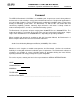
CHAPTER 9 RS232 COMM. Benchmark 2.0LN Low NOx Boiler Installation, Operation and Maintenance Manual GF-120 OMM-0041_0E use the Serial Configuration panel (right image in Figure 9-1) by selecting “Serial” in the left navigation pane. Now, to connect to the remote server, simply click the Open button at the bottom of the dialog box. A new terminal window will pop up and ask you to log in.
GF-120 Benchmark 1.5LN Low NOx Boiler Installation, Operation and Maintenance Manual OMM-0041_0E CHAPTER 9 RS232 COMM. 6. You will have to provide an account name and password in the terminal window to complete the process. 9.
Benchmark 2.0LN Low NOx Boiler CHAPTER 9 RS232 COMM. m0 m1 m2 m3 m4 m5 = = = = = = Installation, Operation and Maintenance Manual GF-120 OMM-0041_0E Default (Operating) Menu Setup Menu Configuration Menu Tuning Menu Calibration Menu Diagnostic Menu 8. To change a value or setting for a displayed menu option, proceed as follows: (a) Enter C, followed by the number to the right of the displayed option to be changed, and then press .
GF-120 Benchmark 1.5LN Low NOx Boiler CHAPTER 9 RS232 COMM. Installation, Operation and Maintenance Manual OMM-0041_0E The Operation Time Log can only be accessed through the RS232 interface using a laptop or other terminal device. Ten operation time records are displayed for each T command entry. The operation time log can be cleared ONLY by factory authorized personnel using the Clear Log option in the Factory menu. NOTE The Sensor (S) Log can store up to 1200 records.
CHAPTER 9 RS232 COMM. Benchmark 2.0LN Low NOx Boiler Installation, Operation and Maintenance Manual GF-120 OMM-0041_0E (This page is intentionally blank) Page 110 of 166 AERCO International Inc. • 100 Oritani Dr.
GF-120 Benchmark 1.5LN Low NOx Boiler Installation, Operation and Maintenance Manual OMM-0041_0E APPENDIX A: APPENDIX A MENU ITEMS MENU ITEM DESCRIPTIONS Table A-1: Boiler Menu Item Descriptions MENU LEVEL & OPTION DESCRIPTION OPERATING MENU Active Setpoint This is the setpoint temperature to which the control is set when operating in the Constant Setpoint, Remote Setpoint or Outdoor Reset Mode.
Benchmark 2.0LN Low NOx Boiler APPENDIX A MENU ITEMS Installation, Operation and Maintenance Manual GF-120 OMM-0041_0E Table A-1: Boiler Menu Item Descriptions MENU LEVEL & OPTION DESCRIPTION SETUP MENU Password Allows password to be entered. Once the valid password (159) is entered, options in the Setup, Configuration and Tuning Menus can be modified. Language Permits selection of English, Spanish or French for displayed messages. Default is English.
GF-120 Benchmark 1.5LN Low NOx Boiler Installation, Operation and Maintenance Manual OMM-0041_0E APPENDIX A MENU ITEMS Table A-1: Boiler Menu Item Descriptions-Continued MENU LEVEL & OPTION DESCRIPTION CONFIGURATION MENU Internal Setpoint Allows internal setpoint to be set. Default is 130°F.
GF-120 Benchmark 2.0LN Low NOx Boiler APPENDIX A MENU ITEMS Installation, Operation and Maintenance Manual OMM-0041_0E Table A-1: Boiler Menu Item Descriptions-Continued MENU LEVEL & OPTION DESCRIPTION CONFIGURATION MENU (Cont.) Pump Delay Timer Specifies the amount of time (0 to 30 min.) to keep the pump running after the unit turns off. Default is zero. Aux Start On Dly Specifies the amount of time to wait (0 to 120 sec.
GF-120 Benchmark 1.5LN Low NOx Boiler Installation, Operation and Maintenance Manual OMM-0041_0E APPENDIX A MENU ITEMS Table A-1: Boiler Menu Item Descriptions MENU LEVEL & OPTION DESCRIPTION CONFIGURATION MENU (Cont.) Deadband High and Deadband Low settings create an “Outlet Temperature” Zone. In which no Valve Position corrections will be attempted. The Deadband ZONE is defined as operating with an Outlet Temperature between Active Setpoint + Deadband High and Active Setpoint – Deadband Low.
Benchmark 2.0LN Low NOx Boiler APPENDIX A MENU ITEMS Installation, Operation and Maintenance Manual GF-120 OMM-0041_0E Table A-1: Boiler Menu Item Descriptions-Continued MENU LEVEL & OPTION DESCRIPTION TUNING MENU Prop Band Generates a fire rate based on the error that exists between the setpoint temperature and the actual outlet temperature. If the actual error is less than the proportional band setting (1 to 120°F), the fire rate will be less than 100%.
GF-120 Benchmark 1.
Benchmark 2.0LN Low NOx Boiler APPENDIX B DISPLAY MESSAGES Installation, Operation and Maintenance Manual GF-120 OMM-0041_0E APPENDIX B: STARTUP, STATUS AND FAULT MESSAGES Table B-1: Startup and Status Messages MESSAGE DEMAND DELAY XX sec DISABLED HH:MM pm, pm MM/DD/YY FLAME PROVEN IGNITION TRIAL XX sec PURGING XX sec STANDBY WAIT WARMUP XX sec Page 118 of 166 DESCRIPTION Displayed if Demand Delay is active. Displayed if ON/OFF switch is set to OFF.
GF-120 Benchmark 1.5LN Low NOx Boiler Installation, Operation and Maintenance Manual OMM-0041_0E APPENDIX B DISPLAY MESSAGES Table B-2: Fault Messages FAULT MESSAGE FAULT DESCRIPTION AIRFLOW FAULT DURING PURGE The Blower Proof Switch opened during purge, or air inlet is blocked. AIRFLOW FAULT DURING IGN The Blower Proof Switch opened during ignition. AIRFLOW FAULT DURING RUN The Blower Proof Switch opened during run. DELAYED INTERLOCK OPEN The Delayed Interlock is open.
APPENDIX B DISPLAY MESSAGES Benchmark 2.0LN Low NOx Boiler Installation, Operation and Maintenance Manual GF-120 OMM-0041_0E Table B-2: Fault Messages (Continued) FAULT MESSAGE FAULT DESCRIPTION OUTDOOR TEMP SENSOR FAULT The temperature measured by the Outdoor Air Sensor is out of range.
GF-120 OMM-0041_0E Benchmark 1.5LN Low NOx Boiler Installation, Operation and Maintenance Manual APPENDIX C TEMPERATURE SENSOR APPENDIX C: SENSOR TEMPERATURE RESISTANCE TABLE C-1: Temperature Sensor Resistance Voltage Chart (Balco) PR1: 10/18/12 TEMP (°F) RES (OHMS) VOLTS* -40 -30 -20 -10 0 10 20 30 40 50 60 70 80 90 100 110 120 130 140 150 160 170 180 190 200 210 220 230 240 250 779.0 797.5 816.3 835.4 854.8 874.6 894.7 915.1 935.9 956.9 978.3 1000.0 1022.0 1044.4 1067.0 1090.0 1113.3 1137.0 1160.
GF-120 Benchmark 2.0LN Low NOx Boiler APPENDIX D RESET RATIO CHARTS Installation, Operation and Maintenance Manual APPENDIX D: OMM-0041_0E INDOOR/OUTDOOR RESET RATIO CHARTS Table D-1: Header Temperature for a Building Reference Temperature of 50ºF RESET RATIO Air Temp 50F 45F 40F 35F 30F 25F 20F 15F 10F 5F 0F -5F -10F -15F -20F 0.6 0.8 1.0 1.2 1.4 1.6 1.8 2.0 2.2 2.
GF-120 Benchmark 1.5LN Low NOx Boiler OMM-0041_0E Installation, Operation and Maintenance Manual APPENDIX D RESET RATIO CHARTS Table D-3: Header Temperature for a Building Reference Temperature of 65ºF RESET RATIO Air Temp 65 60 55 50 45 40 35 30 25 20 15 10 5 0 -5 -10 -15 -20 0.6 0.8 1.0 1.2 1.4 1.6 1.8 2.0 2.2 2.
GF-120 Benchmark 2.0LN Low NOx Boiler APPENDIX D RESET RATIO CHARTS Installation, Operation and Maintenance Manual OMM-0041_0E Table D-5: Header Temperature for a Building Reference Temperature of 75ºF RESET RATIO Air Temp 75F 70F 65F 60F 55F 50F 45F 40F 35F 30F 25F 20F 15F 10F 5F 0F -5F -10F -15F 0.6 0.8 1.0 1.2 1.4 1.6 1.8 2.0 2.2 2.
GF-120 Benchmark 1.5LN Low NOx Boiler OMM-0041_0E Installation, Operation and Maintenance Manual APPENDIX D RESET RATIO CHARTS Table D-7. Header Temperature for a Building Reference Temperature of 90ºF RESET RATIO Air Temp 90F 85F 80F 75F 70F 65F 60F 55F 50F 45F 40F 35F 30F 25F 20F 15F 10F 5F 0F 0.6 0.8 1.0 1.2 1.4 1.6 1.8 2.0 2.2 2.
APPENDIX E BOILER DEFAULTS Benchmark 2.
GF-120 Benchmark 1.
Benchmark 2.0LN Low NOx Boiler APPENDIX E BOILER DEFAULTS Installation, Operation and Maintenance Manual GF-120 OMM-0041_0E Table E-1: Boiler Default Settings (Continued) MENU & OPTION FACTORY DEFAULT Combustion Cal Menu Cal Voltage 16% 1.80 v Cal Voltage 30% 3.20 v Cal Voltage 45% 3.70 v Cal Voltage 60% 3.80 v Cal Voltage 80% 4.60 v Cal Voltage 100% 6.00 v Set Valve Position 0% Blower Output .00 v Page 128 of 166 AERCO International Inc. • 100 Oritani Dr.
GF-120 OMM-0041_0E Benchmark 1.5LN Low NOx Boiler Installation, Operation and Maintenance Manual APPENDIX F PARTS LISTS APPENDIX F: PART AND DIMENSIONAL DRAWINGS PR1: 10/18/12 AERCO International Inc. • 100 Oritani Dr.
APPENDIX F PARTS LISTS Page 130 of 166 Benchmark 2.0LN Low NOx Boiler Installation, Operation and Maintenance Manual AERCO International Inc. • 100 Oritani Dr.
NOTES: PR1: 10/18/12 AERCO International Inc. • 100 Oritani Dr. • Blauvelt, NY 10913 • Ph: 800-526-0288 INTERNATIONAL, INC. NORTHVALE, NJ 07647 *NOT TO SCALE* DRWN BY:SJD DATE:10/12/07 REV SD - A - 730 A Installation, Operation and Maintenance Manual BENCHMARK 1.5 LOW NOx GAS FIRED BOILER ANCHOR BOLT LOCATION AERCO REAR OMM-0041_0E Benchmark 1.
APPENDIX F PARTS LISTS Page 132 of 166 Benchmark 2.0LN Low NOx Boiler Installation, Operation and Maintenance Manual AERCO International Inc. • 100 Oritani Dr.
GF-120 OMM-0041_0E PR1: 10/18/12 Benchmark 1.5LN Low NOx Boiler Installation, Operation and Maintenance Manual AERCO International Inc. • 100 Oritani Dr.
APPENDIX F PARTS LISTS Page 134 of 166 Benchmark 2.0LN Low NOx Boiler Installation, Operation and Maintenance Manual AERCO International Inc. • 100 Oritani Dr.
GF-120 OMM-0041_0E PR1: 10/18/12 Benchmark 1.5LN Low NOx Boiler Installation, Operation and Maintenance Manual AERCO International Inc. • 100 Oritani Dr.
APPENDIX F PARTS LISTS Page 136 of 166 Benchmark 2.0LN Low NOx Boiler Installation, Operation and Maintenance Manual AERCO International Inc. • 100 Oritani Dr.
GF-120 OMM-0041_0E PR1: 10/18/12 Benchmark 1.5LN Low NOx Boiler Installation, Operation and Maintenance Manual AERCO International Inc. • 100 Oritani Dr.
APPENDIX F PARTS LISTS Page 138 of 166 Benchmark 2.0LN Low NOx Boiler Installation, Operation and Maintenance Manual AERCO International Inc. • 100 Oritani Dr.
GF-120 OMM-0041_0E PR1: 10/18/12 Benchmark 1.5LN Low NOx Boiler Installation, Operation and Maintenance Manual AERCO International Inc. • 100 Oritani Dr.
APPENDIX F PARTS LISTS Page 140 of 166 Benchmark 2.0LN Low NOx Boiler Installation, Operation and Maintenance Manual AERCO International Inc. • 100 Oritani Dr.
GF-120 OMM-0041_0E PR1: 10/18/12 Benchmark 1.5LN Low NOx Boiler Installation, Operation and Maintenance Manual AERCO International Inc. • 100 Oritani Dr.
APPENDIX F PARTS LISTS Page 142 of 166 Benchmark 2.0LN Low NOx Boiler Installation, Operation and Maintenance Manual AERCO International Inc. • 100 Oritani Dr.
GF-120 OMM-0041_0E PR1: 10/18/12 Benchmark 1.5LN Low NOx Boiler Installation, Operation and Maintenance Manual AERCO International Inc. • 100 Oritani Dr.
APPENDIX F PARTS LISTS Page 144 of 166 Benchmark 2.0LN Low NOx Boiler Installation, Operation and Maintenance Manual AERCO International Inc. • 100 Oritani Dr.
GF-120 OMM-0041_0E Benchmark 1.5LN Low NOx Boiler Installation, Operation and Maintenance Manual APPENDIX G: PR1: 10/18/12 APPENDIX G PIPING DRAWINGS PIPING DRAWINGS AERCO International Inc. • 100 Oritani Dr.
APPENDIX G PIPING DRAWINGS Page 146 of 166 Benchmark 2.0LN Low NOx Boiler Installation, Operation and Maintenance Manual AERCO International Inc. • 100 Oritani Dr.
GF-120 OMM-0041_0E PR1: 10/18/12 Benchmark 1.5LN Low NOx Boiler Installation, Operation and Maintenance Manual AERCO International Inc. • 100 Oritani Dr.
APPENDIX G PIPING DRAWINGS Page 148 of 166 Benchmark 2.0LN Low NOx Boiler Installation, Operation and Maintenance Manual AERCO International Inc. • 100 Oritani Dr.
GF-120 OMM-0041_0E PR1: 10/18/12 Benchmark 1.5LN Low NOx Boiler Installation, Operation and Maintenance Manual AERCO International Inc. • 100 Oritani Dr.
APPENDIX G PIPING DRAWINGS Page 150 of 166 Benchmark 2.0LN Low NOx Boiler Installation, Operation and Maintenance Manual AERCO International Inc. • 100 Oritani Dr.
GF-120 OMM-0041_0E Benchmark 1.5LN Low NOx Boiler Installation, Operation and Maintenance Manual APPENDIX H: PR1: 10/18/12 APPENDIX H WIRING SCHEMATICS WIRING SCHEMATICS AERCO International Inc. • 100 Oritani Dr.
APPENDIX H WIRING SCHEMATICS Benchmark 2.0LN Low NOx Boiler Installation, Operation and Maintenance Manual GF-120 OMM-0041_0E (This page intentionally blank) Page 152 of 166 AERCO International Inc. • 100 Oritani Dr.
GF-120 Benchmark 1.5LN Low NOx Boiler OMM-0041_0E Installation, Operation and Maintenance Manual PR1: 10/18/12 AERCO International, Inc. • 100 Oritani Dr.
APPENDIX H WIRING Page 154 of 166 Benchmark 1.5LN Low NOx Boiler GF-120 Installation, Operation & Maintenance Manual OMM-0041_0E AERCO International, Inc. • 100 Oritani Dr.
GF-120 Benchmark 1.5LN Low NOx Boiler OMM-0041_0E Installation, Operation & Maintenance Manual PR1: 10/18/12 AERCO International, Inc. • 100 Oritani Dr.
APPENDIX H WIRING Page 156 of 166 Benchmark 1.5LN Low NOx Boiler GF-120 Installation, Operation & Maintenance Manual OMM-0041_0E AERCO International, Inc. • 100 Oritani Dr.
GF-120 Benchmark 1.5LN Low NOx Boiler APPENDIX I PERIODIC TESTING Installation, Operation and Maintenance Manual OMM-0041_0E APPENDIX I: RECOMMENDED PERIODIC TESTING CHECK LIST WARNING NOTE: Periodic testing of all boiler controls and safety devices is required to determine that they are operating as designed. Precautions shall be taken while tests are being performed to protect against bodily injury and property damage.
APPENDIX I PERIODIC TESTING Benchmark 2.0LN Low NOx Boiler Installation, Operation and Maintenance Manual GF-120 OMM-0041_0E (This page is intentionally blank) Page 158 of 166 AERCO International Inc. • 100 Oritani Dr.
GF-120 OMM-0041_0E Benchmark 1.5LN Low NOx Boiler Installation, Operation and Maintenance Manual APPENDIX J CONTROL PANEL APPENDIX J: BENCHMARK CONTROL PANEL FEATURES Figure J-1: Control Panel Exploded View PR1: 10/18/12 AERCO International Inc. • 100 Oritani Dr.
Benchmark 2.0LN Low NOx Boiler SHELL HARNESS CONNECTOR (19 PIN) P3 EXT. SENSOR/COMM HARNESS CONNECTOR (24 PIN) TO INPUT/OUTPUT (I/O) BOX SENSOR HARNESS CONNECTOR (7 PIN) P1 A/F VALVE HARNESS CONNECTOR (16 PIN) P2 GAS TRAIN HARNESS CONNECTOR (9 PIN) P5 INTERLOCK HARNESS CONNECTOR (16 PIN) TO INPUT/OUTPUT (I/O) BOX OMM-0041_0E P6 Installation, Operation and Maintenance Manual GF-120 P4 APPENDIX J CONTROL PANEL Figure J-2: Control Panel Rear Panel Page 160 of 166 AERCO International Inc.
GF-120 Benchmark 1.5LN Low NOx Boiler OMM-0041_0E APPENDIX K SPARE PARTS Installation, Operation and Maintenance Manual APPENDIX K: RECOMMENDED SPARE PARTS LISTS NOTE Refer to the Parts List Illustrations in Appendix F for the locations of the recommended and optional spare parts listed in the following Tables.
Appendix K Spare Parts Benchmark 2.0LN Low NOx Boiler Installation, Operation and Maintenance Manual GF-120 OMM-0041_0E (This page is intentionally blank) Page 162 of 166 AERCO International Inc. • 100 Oritani Dr.
GF-120 OMM-0041_0E Benchmark 1.5LN Low NOx Boiler Installation, Operation and Maintenance Manual LIMITED WARRANTY: BENCHMARK GAS-FIRED BOILER PRESSURE VESSEL/ 439SS HEAT EXCHANGER: 10 YEAR NON-PRORATED FROM SHIPMENT The pressure vessel/heat exchanger shall carry a 10 year non-prorated, limited warranty from date of shipment against any condensate corrosion, thermal stress failure, mechanical defects or workmanship. Operation of the boiler using contaminated air will void the warranty.
(This page is intentionally blank) Page 164 of 166 AERCO International Inc. • 100 Oritani Dr.
GF-120 OMM-0041_0E Benchmark 1.5LN Low NOx Boiler Installation, Operation and Maintenance Manual (This page is intentionally blank) PR1: 10/18/12 AERCO International Inc. • 100 Oritani Dr.
© AERCO International, Inc., 2012 Page 166 of 166 AERCO International Inc. • 100 Oritani Dr.