
Manual

CHAPTER 3
OPERATION
PR1: 10/18//12 AERCO International Inc. • 100 Oritani Dr. • Blauvelt, NY 10913 • Ph: 800-526-0288 Page 45 of 166
GF-120
OMM-0041 0E
Benchmark 1.5LN Low NOx Boiler
Installation, Operation and Maintenance Manual
After 2 seconds of continuous flame, Flame Proven will be displayed and the flame 7.
strength will be indicated. After 5 seconds, the current date and time will be displayed in
place of the flame strength.
With the unit firing properly, it will be controlled by the temperature controller circuitry. 8.
The boiler’s VALVE POSITION will be continuously displayed on the front panel
bargraph.
Once the demand for heat has been satisfied, the Control Box will turn off the dual SSOV gas
valves. The blower relay will be deactivated and the Air/Fuel Valve will be closed. Standby will
be displayed.
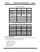
3.10 START/STOP LEVELS
The start and stop levels are the Air/Fuel Valve positions (% open) that start and stop the unit,
based on load. These levels are Factory preset as follows:
Start Level: 20%
Stop Level: 16%
Normally, these settings should not require adjustment.
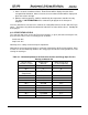
Note that the energy input of the boiler is not linearly related to the Air/Fuel Valve position. Refer
to Table 3-7 for the relationship between the energy input and Air/Fuel Valve position for a unit
running on natural gas.
Table 3-7: Relationship Between Air/Fuel Valve Position and Energy Input For Unit
Running on Natural Gas
Air/Fuel Valve
Position (% Open)
Energy Input
(BTU/Hr)
Boiler Energy Input
(% of Full Capacity)
0%
0
0
10%
0
0
16%
(Stop Level)
75,000
5.0%
20%
157,000
10%
30%
310,000
21%
40%
534,000
36%
50%
783,000
52%
60%
970,000
65%
70%
1,140,000
76%
80%
1,240,000
83%
90%
1,370,000
91%
100%
1,500,000
100%