
Manual


CHAPTER 5
MODE OF OPERATION
PR1: 10/18//12 AERCO International Inc. • 100 Oritani Dr. • Blauvelt, NY 10913 • Ph: 800-526-0288 Page 63 of 166
GF-120
OMM-0041 0E
Benchmark 1.5LN Low NOx Boiler
Installation, Operation and Maintenance Manual
5.4 REMOTE SETPOINT MODES
The unit’s setpoint can be remotely controlled by an Energy Management System (EMS) or
Building Automation System (BAS). The Remote Setpoint can be driven by a current or voltage
signal within the following ranges:
• 4-20 mA/1-5 Vdc
• 0-20 mA/0-5 Vdc
The factory default setting for the Remote Setpoint mode is 4 - 20 mA/1 - 5 Vdc. With this
setting, a 4 to 20 mA/1 to 5 Vdc signal, sent by an EMS or BAS, is used to change the unit's
setpoint. The 4 mA/1V signal is equal to a 40°F setpoint while a 20 mA /5V signal is equal to a
240°F setpoint. When a 0 to 20 mA/0 to 5 Vdc signal is used, 0 mA is equal to a 40°F setpoint.
In addition to the current and voltage signals described above, the Remote Setpoint mode can
also driven by a RS485 Modbus Network signal from an EMS or BAS.
The Remote Setpoint modes of operation can be used to drive single as well as multiple units.
NOTE
If a voltage, rather than current signal is used to control the
remote setpoint, a DIP switch adjustment must be made on the
PMC Board located in the Control Panel Assembly. Contact your
local AERCO representative for details.
In order to enable the Remote Setpoint Mode, the following menu setting must be made in the
Configuration Menu:
MENU OPTION SETTING
Boiler Mode Remote Setpoint
Remote Signal 4-20mA/1-5V,
0-20mA/0-5V, or
Network
Refer to paragraph 3.3 for detailed instructions on changing menu options.
If the Network setting is selected for RS485 Modbus operation, a valid Comm Address must be
entered in the Setup Menu. Refer to Modbus Communication Manual GF-114 for additional
information.
While it is possible to change the settings of temperature related functions, the unit is factory
preset with settings that work well in most applications. It is suggested that an AERCO
representative be contacted, prior to changing any temperature related function settings. For
descriptions of temperature-related functions and their factory defaults, refer to Appendices A
and E.
5.4.1
Remote Setpoint Field Wiring
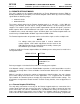
The only wiring connections necessary for the Remote Setpoint mode are connection of the
remote signal leads from the source to the unit’s I/O Box. The I/O Box is located on the front
panel of the boiler. For either a 4-20mA/0-5V or a 0-20mA/0-5V setting, the connections are
made at the ANALOG IN terminals in the I/O Box. For a Network setting, the connections are
made at the RS-485 COMM terminals in the I/O Box. The signal must be floating, (ungrounded)