Instruction No. GF-114 AERCO INTERNATIONAL, Inc., Northvale, New Jersey, 07647 USA MODBUS ® Communication Manual For C-More Boiler Controllers and Boiler Management Systems ® Modbus is a registered trademark of AEG Modicon Printed in U.S.
MODBUS COMMUNICATION MANUAL TABLE OF CONTENTS PAGE PARA. SECTION 1 – INTRODUCTION & GENERAL DESCRIPTION 1-1 1.1 INTRODUCTION 1-1 1.2 AERCO BMS AND C-MORE CONTROLLER MODELS COVERED 1-1 1.3 MINIMUM MODBUS SUPPORT REQUIREMENTS 1-1 1.3.1 Communication Medium 1-2 1.3.2 Address Support 1-3 1.3.3 Modbus Transmission Modes 1-3 1.3.4 Timing Specifications 1-3 1.4 MODBUS FUNCTION SET SUPPORT 1-3 1.5 EXCEPTION RESPONSES 1-4 1.
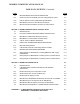
MODBUS COMMUNICATION MANUAL TABLE OF CONTENTS - Continued PAGE PARA. 3.3 BMS STANDARD APPLICATION OPERATIONS 3-3 3.3.1 Password Protection For BMS Input and Holding Register Access 3-3 3.3.2 Remote Setpoint Control of BMS Slave By EMS Master 3-3 3.3.3 BMS Master Control of C-More Slaves Via Network 3-4 3.3.4 BMS Combination Mode Boiler Controller of C-More Slaves 3-4 SECTION 4 – MODBUS NETWORK SETUP & INSTALLATION 4-1 4.1 INTRODUCTION 4-1 4.
MODBUS COMMUNICATION MANUAL SECTION 1 INTRODUCTION & GENERAL DESCRIPTION 1.1 INTRODUCTION. The information contained in this manual provides general guidelines for implementing a Modbus® communications network utilizing AERCO’s Boiler Management System (BMS) and C-More Boiler Controllers. All Modbus networks are implemented utilizing a Master-Slave technique where only one device, the Master, can initiate a communication sequence.
MODBUS COMMUNICATION MANUAL Table 1-1.
MODBUS COMMUNICATION MANUAL 1.3.1.2 BMS Master To C-More Boiler Controller Slaves Up to a total of 32 C-More Boiler Controllers can be connected to a BMS Master on the Modbus Network. Multi-point drop network connections are made using shielded, twisted-pair wire. In addition to the Modbus Network Boilers, up to 8 additional Legacy Boilers can be connected using the BMS Pulse Width Modulation (PWM) wiring connection provided on connector J2. 1.3.1.
MODBUS COMMUNICATION MANUAL Table 1-2. Required Function Code Set Function Code Function Name 03 Read Holding Register (Read Multiple Registers) 04 Read Input Registers 06 Preset (Write) Single Register 08 Diagnostics (See Table 1-3 for supported Sub-Function Codes) 17 Report Slave ID Table 1-3. Minimum Diagnostic (Function Code 08) Sub-Function Set Sub-Function Code Sub-Function Name Comments 00 Return Query Data Loop-Back 01 Restart Communications Options Resets the Slave.
MODBUS COMMUNICATION MANUAL Table 1-4. Minimum Exception Code Set Exception Code Description Comments 01 Illegal Function The function code received is not valid or is not supported. 02 Illegal Data Address The data address received is invalid or is not accessible due to security setting. 03 Illegal Data Value The data value received is not valid 1.6 PHRASES, ABBREVIATIONS & ACRONYMS The phrases, abbreviations and acronyms used in this manual are listed in Table 1-5. Table 1-5.
MODBUS COMMUNICATION MANUAL SECTION 2 STANDARD REGISTER ASSIGNMENTS 2.1 INTRODUCTION This Section provides the standard data register addresses assigned to the AERCO and CMore Boiler Controllers and the AERCO Boiler Management System (BMS). These data registers consist of Input Registers and Holding Registers. All register addresses provided throughout this manual are expressed as hexadecimal numbers. 2.1.
MODBUS COMMUNICATION MANUAL 2.2 C-MORE BOILER CONTROLLER STANDARD REGISTER ASSIGNMENTS 2.2.1 C-More Boiler Controller Standard Input Register Assignments The Read Only Input Register addresses are listed in Table 2-1 which follows: Table 2-1.
MODBUS COMMUNICATION MANUAL Table 2-1.
MODBUS COMMUNICATION MANUAL Table 2-1.
MODBUS COMMUNICATION MANUAL 2.2.2 C-More Boiler Controller Standard Holding Register Assignments The Read/Write Input Register address assignments are listed in Table 2-2 which follows. Unless otherwise specified, all Holding Register menu items are Read/Write (R/W) Table 2-2. C-More Controller Standard Holding Register Address Mapping Modbus Data Address (Hex) Menu Item Units and Range Comments 0x0000 Net Remote Set Point DEGREES_1 (0 to 1000) See Appendix A, Tables A-2 and A-3 for Conversions.
MODBUS COMMUNICATION MANUAL Table 2-2. C-More Controller Standard Holding Register Address Mapping-Cont.
MODBUS COMMUNICATION MANUAL Table 2-2. C-More Controller Standard Holding Register Address Mapping-Cont. Modbus Data Address (Hex) Menu Item Units and Range Comments 0x0018 Failsafe Mode enum (0, 1) 0=Shutdown 1=Constant Setpoint Default = 0 (Shutdown) 0x0019 Low Fire Timer SEC_UNITS (2 to 60) 1count/sec Default = 2 sec. 0x001A Prop Band ABS_DEG_1 (0 to 1000) See Appendix A, Tables A-2 and A-3 for Conversions 0x001B Integral Gain 0.00 to 2.00 (0.
MODBUS COMMUNICATION MANUAL Table 2-2. C-More Controller Standard Holding Register Address Mapping-Cont. Modbus Data Address (Hex) Menu Item 0x0043 Sensor Log Interval Enum (0 to 8) 0 = Off 1 = 1 Min. 2 = 5 Min. 3 = 15 Min. 4 = 30 Min. 5 = 1 Hr. 6 = 6 Hrs 7 = 12 Hrs. 8 = 24 Hrs.
MODBUS COMMUNICATION MANUAL 2.3 BMS CONTROLLER STANDARD REGISTER ASSIGNMENTS 2.3.1 BMS Controller Standard Input Register Assignments The Read Only Input Register address assignments for the BMS are listed in Table 2-3 which follows on the next page. Table 2-3.
MODBUS COMMUNICATION MANUAL Table 2-3. BMS Standard Input Register Address Mapping-Cont. Modbus Data Address (Hex) Menu Item Units and Range Comments 0x0011 Boiler 1 Status 119 = Not On-Line 120 = On-Line But Not Fired 1–40 = Fired & Sequence Boilers 1 - 8 are referred to as the Legacy Boilers.
MODBUS COMMUNICATION MANUAL Table 2-3. BMS Standard Input Register Address Mapping-Cont.
MODBUS COMMUNICATION MANUAL Table 2-3. BMS Standard Input Register Address Mapping-Cont.
MODBUS COMMUNICATION MANUAL 2.3.2 BMS Controller Standard Holding Register Assignments The Holding Register address assignments for the BMS are listed in Table 2-3 which follows. Unless otherwise specified, all Holding Register Menu items are Read/Write (R/W). Table 2-4.
MODBUS COMMUNICATION MANUAL Table 2-4. BMS Standard Holding Register Address Mapping Modbus Data Address (Hex) Menu Item Units and Range Default/Comments 0x0012 Derivative Gain -2.00 to 2.00 (0.00 increments) Default = 0.
MODBUS COMMUNICATION MANUAL Table 2-4. BMS Standard Holding Register Address Mapping-Cont.
MODBUS COMMUNICATION MANUAL Table 2-4. BMS Standard Holding Register Address Mapping-Cont.
MODBUS COMMUNICATION MANUAL Table 2-4. BMS Standard Holding Register Address Mapping-Cont.
MODBUS COMMUNICATION MANUAL Table 2-4. BMS Standard Holding Register Address Mapping-Cont.
MODBUS COMMUNICATION MANUAL Table 2-4. BMS Standard Holding Register Address Mapping-Cont.
MODBUS COMMUNICATION MANUAL SECTION 3 STANDARD APPLICATION OPERATIONS 3.1 INTRODUCTION This Section describes the standard application operations for AERCO C-More Boiler Controllers and the AERCO Boiler Management System (BMS) and how they are achieved utilizing Modbus. Paragraphs 3.2 through 3.2.7 provide information for the C-More Boiler Controllers which can only function as Slaves in a Modbus Network. Paragraphs 3.3 through 3.3.
MODBUS COMMUNICATION MANUAL 3.2.2 Simultaneous RS232 & RS485 Access to C-More Controller Variables As previously mentioned, read and write access of the C-More Controller variables are protected from unauthorized access by an internal security level hierarchy.
MODBUS COMMUNICATION MANUAL 3.2.6 Broadcast Commands Address 0 is reserved for Broadcast Messages sent by the Modbus Master. At the current time, only two holding register variables can be written by broadcast to the C-More Controller Slaves. These variables are Net Remote Setpoint and Net Direct Drive (addresses 0x0000, 0x0001). No password is required to write either of these variables. Broadcast write commands to all other holding registers will be ignored.
MODBUS COMMUNICATION MANUAL To enable the Remote Setpoint Mode, the parameters “Remote Signal” and “RS232 Mode” must be set to “Network” and “Modbus” respectively. These parameter are stored in Standard Holding Register addresses 0x0056 and 0x0057 respectively. Also, ensure that the RS232 Baud Rate setting (address 0x0058) matches the EMS Baud Rate being used.
MODBUS COMMUNICATION MANUAL SECTION 4 MODBUS NETWORK HARDWARE SETUP & INSTALLATION 4.1 INTRODUCTION This Section provides basic information on planning and setup of a Modbus Communication Network utilizing AERCO C-More Boiler Controllers and a Boiler Management System (BMS). It also provides basic information on Modbus Network setup utilizing AERCO BMS/C-More Slaves with a Master EMS (or BAS) provided by other manufacturers. 4.
MODBUS COMMUNICATION MANUAL Figure 4-2. BMS Left Side View 4-2 AUX FLT ALARM JP4 SYS START 14 SET 15 BACK 16 13 INT2 11 12 INT1 JP12 4-20 +9 MA -10 SHIELD 8 REF 6 TEMP 7 HDR 4 TEMP SEN 5 SHIELD 3 JP3 OUT 1 AIR SEN 2 JP11 +15 BLR 8 -16 BLR +13 7 -14 -10 BLR +11 6 -12 -8 +9 BLR 5 +7 BLR 4 +5 BLR 3 -6 +3 BLR 2 -4 JP2 BLR +1 1 -2 Simplified block diagrams showing the internal and external connection options between the BMS and EMS are shown in Figure 4-3.
MODBUS COMMUNICATION MANUAL Figure 4-3.
MODBUS COMMUNICATION MANUAL Figure 4-3.
MODBUS COMMUNICATION MANUAL Figure 4-4. BMS RS232 & RS485 Connectors 4.2.2 BMS Master To C-More Boiler Controller Slaves Wiring connections for Modbus operation between a BMS Master and C-More Boiler Controller Slaves are made between the BMS internal RS485 connector (Figure 4-1) and the I/O Box for the associated C-More Boiler Controller. The BMS internal RS485 connector pinouts are shown in Figure 4-4. The RS485 COMM connections at each Boiler’s I/O Box are shown in Figure 4-5.
MODBUS COMMUNICATION MANUAL KC1000 BENCHMARK OUTDOOR SENSOR IN SENSOR COMMON AUX SENSOR IN REMOTE INTL'K IN EXHAUST SWITCH IN DELAYED INTL'K IN NOT USED NOT USED NC COM NO + ANALOG IN+ B.M.S. (PWM) IN - NC COM NO RS-485 COMM. AUX RELAY 120 VAC, 5A, RES NOT USED SHIELD mA OUT FAULT RELAY 120 VAC, 5A, RES NOTE DO NOT TERMINATE THE SHIELDS OF THE RS485 LEADS TO THE GROUND (G) TERMINAL. THE SHIELDS MUST BE TERMINATED AT THE SOURCE ENDS ONLY.
MODBUS COMMUNICATION MANUAL 4.2.3 C-More Slaves To BMS or EMS Master Wiring connections between a BMS Master and up to 32 Network C-More Boiler Controller Slaves are made directly between the BMS internal RS485 terminals (Figure 4-4) and the RS485 COMM terminals in each Boiler’s I/O Box (Figure 4-5). If a third-party EMS Master is used in place of the BMS, the Modbus Network connections will depend on the available communication port(s) on the EMS.
MODBUS COMMUNICATION MANUAL CAUTION The C-More Boiler Controller Printed Circuit Boards contain electronic components that are sensitive to electrostatic discharge (ESD). Prior to performing the following steps, put on an anti-static wrist strap and connect the clip lead to earth ground. Failure to observe this precaution may result in permanent damage to on-board ESD-sensitive components. 4. Put on an anti-static wrist strap and attach the clip lead to earth ground. 5.
MODBUS COMMUNICATION MANUAL Figure 4-7.
MODBUS COMMUNICATION MANUAL RIBBON CABLE CONNECTOR (J1) SEE DETAIL “A” CBS1 J1 RS485 R55 R49 C40 R50 C38 R54 R8 C10 R7 C11 R52 U7 R46 C36 R81 C37 R53 U6 R4 R62 C9 U3 R9 J3 R12 B1 C64 HB U21 C5 R75 C6 C1 C2 R76 R77 C43 R65 C16 C19 C29 C31 C28 C55 R70 C23 C22 R24 R25 R26 R28 C18 C26 R27 U4 C34 C20 R18 R16 U18 C45 C33 R42 R43 R41 R40 R39 C35 C32 C27 R32 R14 R17 C63 R61 R59 C42 R60 U5 R38 R36 R35 U19 C56 R71 R73 R72 CR1 C54 R63 C41 R64 C30 R37 U16 DS3 CR2
MODBUS COMMUNICATION MANUAL 4.4 MODBUS NETWORK WIRING DIAGRAMS Sample Modbus Network wiring diagrams for the basic circuit configurations are provided in paragraphs 4.4.1 through 4.4.3. It should be noted that these diagrams are only intended as a guide and do not include all possible scenarios. If a third-party EMS is being utilized, refer to the manufacturer’s manual prior to attempting any network wiring connections.
4-12 RS485 PORT RS232 PORT 4-WIRE RS485 J2P PWM TERMINALS ------- --- MODBUS COMMUNICATION MANUAL
MODBUS COMMUNICATION MANUAL 4-13
MODBUS COMMUNICATION MANUAL 4-14
MODBUS COMMUNICATION MANUAL SECTION 5 MODBUS SOFTWARE SETUP 5.1 INTRODUCTION This Section provides the information necessary to configure the AERCO C-More Boiler Controllers and a Boiler Management System (BMS) for operation on a Modbus Network. It also provides the basic setup procedures to operate the C-More Boiler Controller and BMS in each available Modbus Mode. 5.
MODBUS COMMUNICATION MANUAL Once the Comm Address has been entered, the C-More Boiler Controller can be accessed the Modbus Network Master (BMS or EMS). 5.2.2 Modbus Direct Drive Control and Monitoring Modbus Direct Drive Control of the C-More Boiler Controller is set up as follows: 1. Enter and store a valid Comm Address using the procedures in paragraph 5.2.1. 2.
MODBUS COMMUNICATION MANUAL NOTE The AERCO BMS can function as either a Slave or a Master on a Modbus Network. Paragraph 5.3 provides the programming setup procedures when the BMS is a Slave to an EMS (or BAS). Paragraph 5.4 provides the programming setup procedures when the BMS is the controlling Master for C-More Boiler Controllers. 5.
MODBUS COMMUNICATION MANUAL 5.3.2 BMS Modbus Remote Setpoint Control By An EMS Master To configure the BMS for Remote Setpoint Control from an EMS Master, proceed as follows: 1. Press the FIELD ADJ key on the BMS front panel to enter the Field Adjust Mode. The yellow LED on the key should be lit. 2. Press the AIR TEMP key until RS232 MODE is shown on the top line of the display. If necessary, press the ▲ or ▼ arrow key until MODBUS SLAVE appears in the second line of the display. 3.
MODBUS COMMUNICATION MANUAL 5.4 BMS SETUP AS MASTER TO C-MORE BOILER CONTROLLERS To set up the BMS as a Master to Control C-More Boiler Slaves, proceed as follows: 1. Press the FIELD ADJ key on the BMS front panel to enter the Field Adjust Mode. The yellow LED on the key should be lit. 2. Press the HDR TEMP key until RS485 BAUDRATE is shown on the top line of the display. Press the ▲ and ▼ arrow keys if necessary to set the baud rate to 9600. 3.
MODBUS COMMUNICATION MANUAL The BMS is now programmed to control the Networked Boilers, as well as any Legacy Boilers connected to it.
MODBUS COMMUNICATION MANUAL APPENDIX A C-MORE BOILER CONTROLLER STATUS & FAULT MESSAGES AND CONVERSION EQUATIONS A-1
MODBUS COMMUNICATION MANUAL Table A-1. Status and Fault Messages Code MESSAGE DESCRIPTION 1 DISABLED HH:MM pm MM/DD/YY 2 STANDBY 3 DEMAND DELAY XX sec 4 PURGING XX sec 5 IGNITION TRIAL XX sec Displayed during ignition trial of startup sequence. The duration of cycle counts up in seconds. 6 FLAME PROVEN Displayed after flame has been detected for a period of 2 seconds. Initially, the flame strength is shown in %.
MODBUS COMMUNICATION MANUAL Table A-1. Status and Fault Messages –Cont. Code MESSAGE DESCRIPTION 17 IGN SWTCH OPEN DURING IGNITION The Ignition Position Limit switch on the Air/Fuel valve opened during ignition. 18 AIRFLOW FAULT DURING IGN The Blower Proof Switch opened during ignition. 19 AIRFLOW FAULT DURING RUN The Blower Proof Switch opened during run. 20 SSOV FAULT DURING IGN The SSOV switch closed or failed to open during ignition.
MODBUS COMMUNICATION MANUAL Table A-1. Status and Fault Messages –Cont. Code MESSAGE DESCRIPTION 39 DIRECT DRIVE SIGNAL FAULT 40 REMOTE SETPT SIGNAL FAULT The remote setpoint signal is not present or is out of range. 41 OUTDOOR TEMP SENSOR FAULT The temperature measured by the Outdoor Air Sensor is out of range. 42 OUTLET TEMP SENSOR FAULT The temperature measured by the Outlet Sensor is out of range. 43 FFWD TEMP SENSOR FAULT The temperature measured by the FFWD Sensor is out of range.
MODBUS COMMUNICATION MANUAL Table A-2.