
Specifications


MODBUS COMMUNICATION MANUAL
1-2
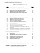
Table 1-1. Modbus Communication and Support Requirements
Characteristic Requirement
Communication Medium:
• EMS Master-To-BMS Slave
• BMS Master-To-C-More Slave
• EMS Master-To- C-More Slave
RS232 (or RS485 With Optional Converter)
RS485, 2-Wire Differential Bus With Shield
RS485, 2-Wire Differential Bus With Shield
Allowable Cable Lengths
• RS232
• RS485
• PWM
50 Feet, Maximum
4,000 Feet, Maximum
1,000 Feet, Maximum
Address Support From Master:
• BMS
• C-More Controller (Slave)
• Broadcast Messages
128 to 247 (From a Master EMS)
1 to 127 (From Master BMS or EMS)
Address 0 is Reserved for Broadcast Messages
Transmission Mode Support RTU (Remote Terminal Unit)
Timing Specifications:
• Baud Rate
Message Framing
• Character Framing
• Heartbeat Timeout
Fixed at 9600 For C-More
Adjustable For BMS: 2400, 4800, 9600, 14.4k, 19.2k
Default = 9600
Silent period of at least 3.5 character times Before
first
character and After
last character of message
No more than 1.5 character times of silence between
received and transmitted characters
Fixed at 10 seconds For C-More
Adjustable For BMS: 5 to 240 Seconds
1.3.1 Communication Medium
The communication medium for each of the possible Modbus network configurations may vary
depending on the Master/Slave scenario being implemented. Detailed installation procedures
and wiring diagrams for the configurations described in the following paragraphs are provided in
Section 4 of this manual.
1.3.1.1
EMS Master To BMS Slave
The Modbus network connections between the EMS and BMS will depend on the type of port
provide on the EMS Master. If the EMS contains a RS232 port, a direct connection can be
made directly to the BMS RS232 port. For optimum results the wire length between the EMS
and BMS RS232 connection should not exceed 50 feet. If the EMS Master contains a RS485
port, a RS485-to-RS232 converter will be required to implement the Modbus network.