Instruction No. GF-117 AERCO INTERNATIONAL, Inc., Northvale, New Jersey, 07647 USA Installation, Operation & Maintenance Instructions Benchmark 3.0 Dual-Fuel Series Gas Fired Low NOx Boiler System Natural Gas and Propane Fired, Condensing, Forced Draft Hot Water Boiler 3,000,000 BTU/H Input Applicable to Serial Numbers G-09-0298 and above Printed in U.S.A.
Telephone Support Direct to AERCO Technical Support (8 to 5 pm EST, Monday through Friday): 1-800-526-0288 The information contained in this installation, operation and maintenance manual is subject to change without notice from AERCO International, Inc. AERCO International, Inc. 159 Paris Avenue Northvale, NJ 07647-0128 www.aerco,com © AERCO International, Inc.
CONTENTS GF-117 - AERCO BENCHMARK 3.0 DUAL-FUEL LOW NOx BOILER Operating & Maintenance Instructions FOREWORD A Chapter 1 – SAFETY PRECAUTIONS Para. 1-1 1-2 Subject Warnings & Cautions Emergency Shutdown Page 1-1 1-2 1-1 Para. 1-3 Subject Prolonged Shutdown Chapter 2 – INSTALLATION Para. 2.1 2.2 2.3 2.4 2.5 2.6 2.7 2.
CONTENTS Chapter 5 – MODE OF OPERATION Para. 5.1 5.2 5.3 5.4 5.5 Subject Introduction Indoor/Outdoor Reset Mode Constant Setpoint Mode Remote Setpoint Mode Direct Drive Modes 5-1 Page 5-1 5-1 5-2 5-2 5-3 Para. 5.6 5.7 Subject Boiler Management System (BMS) Combination Control System (CCS) Page 5-4 5-5 Chapter 6 – SAFETY DEVICE TESTING PROCEDURES 6-1 Para. 6.1 6.2 Page 6-4 6-5 6.3 6.4 6.5 6.6 6.
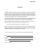
CONTENTS APPENDICES App A B C D E Subject Boiler Menu Item Descriptions Startup, Status and Fault Messages Temperature Sensor Resistance Chart Indoor/Outdoor Reset Ratio Charts Boiler Default Settings WARRANTIES Page A-1 B-1 C-1 D-1 E-1 App F G H I J K Subject Dimensional and Part Drawings Piping Drawings Wiring Schematics Recommended Periodic Testing Checklist Benchmark Control Panel Views Benchmark 3.
FOREWORD Foreword The AERCO Benchmark 3.0 Dual-Fuel Boiler is a modulating unit. It represents a true industry advance that meets the needs of today's energy and environmental concerns. Designed for application in any closed loop hydronic system, the Benchmark's modulating capability relates energy input directly to fluctuating system loads. The Benchmark 3.
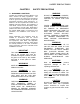
SAFETY PRECAUTIONS CHAPTER 1 SAFETY PRECAUTIONS 1.1 WARNINGS & CAUTIONS Installers and operating personnel MUST, at all times, observe all safety regulations. The following warnings and cautions are general and must be given the same attention as specific precautions included in these instructions. In addition to all the requirements included in this AERCO Instruction Manual, the installation of units MUST conform with local building codes, or, in the absence of local codes, ANSI Z223.
SAFETY PRECAUTIONS 1.2 EMERGENCY SHUTDOWN 1.3 PROLONGED SHUTDOWN If overheating occurs or the gas supply fails to shut off, close the manual gas shutoff valve (Figure 1-1) located external to the unit. After prolonged shutdown, it is recommended that the startup procedures in Chapter 4 and the safety device test procedures in Chapter 6 of this manual be performed, to verify all systemoperating parameters.
INSTALLATION CHAPTER 2 INSTALLATION 2.1 INTRODUCTION • Pressure/Temperature Gauge This Chapter provides the descriptions and procedures necessary to unpack, inspect and install the AERCO Benchmark 3.0 Dual-Fuel Boiler. Brief descriptions are also provided for each available mode of operation. Detailed procedures for implementing these modes are provided in Chapter 5. • Spare Spark Igniter 2.2 RECEIVING THE UNIT Each Benchmark 3.0 Dual-Fuel System is shipped as a single crated unit.
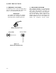
INSTALLATION Figure 2-1 Benchmark 3.0 Dual Fuel Boiler Clearances WARNING KEEP THE UNIT AREA CLEAR AND FREE FROM ALL COMBUSTIBLE MATERIALS AND FLAMMABLE VAPORS OR LIQUIDS. CAUTION While packaged in the shipping container, the boiler must be moved by pallet jack or forklift from the FRONT ONLY. 2.4.2 Setting the Unit The unit must be installed on a 4 inch to 6 inch housekeeping pad to ensure proper condensate drainage.
INSTALLATION 2.4.3 Removal of Support Rod Prior to installation of water supply and return piping, the 24” threaded rod shown in Figure 2-3 must be removed. This rod is installed prior to shipment from the factory to prevent damage to the insulated metal flex hose on the hot water supply outlet of the boiler. In order to install the water supply piping, this rod must be removed as follows: 1. Refer to Figure 2-3 and back off the hex nut on the outlet side of the flex hose.
INSTALLATION NOTE A EXHAUST MANIFOLD CONDENSATE TRAP A The condensate trap described in the following steps can be installed on the floor behind the unit as shown in Figure 26. There will be sufficient downward slope from the drain pipe to the trap inlet to drain the condensate by gravity. Ensure that the outlet hose from the trap slopes away (down) from the trap. DRAIN SHELL DRAIN VALVE B CONNECTING MANIFOLD 2. Install 3/4” NPT nipples in the tapped inlet and outlet of the condensate trap.
INSTALLATION 2.7 GAS SUPPLY PIPING The AERCO Benchmark 3.0 Gas Components and Supply Design Guide, GF-3030 must be consulted prior to designing or installing any gas supply piping. WARNING NEVER USE MATCHES, CANDLES, FLAMES OR OTHER SOURCES OF IGNITION TO CHECK FOR GAS LEAKS. CAUTION Many soaps used for gas pipe leak testing are corrosive to metals. Therefore, piping must be rinsed thoroughly with clean water after leak checks have been completed.
INSTALLATION 2.7.3 IRI Gas Train Kit 2.8.1 Electrical Power Requirements The IRI gas train is an optional gas train configuration which is required in some areas for code compliance or for insurance purposes. The IRI gas train is factory pre-piped and wired. See Appendix F, Drawing AP-A-803 for details. The AERCO Benchmark 3.0 Dual-Fuel Boiler is available in two different AC power configurations: 2.8 AC ELECTRICAL POWER WIRING The AERCO Benchmark 3.
INSTALLATION 2.9 MODES OF OPERATION AND FIELD CONTROL WIRING The Benchmark 3.0 Dual-Fuel Boiler is available in several different modes of operation. While each unit is factory configured and wired for its intended mode, some additional field wiring may be required to complete the installation. This wiring is typically connected to the Input/Output (I/O) Box located on the lower portion of the unit front panel (Figure 2-10) behind the removable front door.
INSTALLATION 2.9.1 Constant Setpoint Mode The Constant Setpoint Mode is used when it is desired to have a fixed setpoint that does not deviate. No wiring connections, other than AC electrical power connections, are required for this mode. However, if desired, fault monitoring or enable/disable interlock wiring can be utilized (see paragraphs 2.9.9.1 and 2.9.10). Mode) or firing rate (Direct Drive Mode) of the Boiler.
INSTALLATION This feature allows the boiler to be enabled or disabled based on the outdoor air temperature. The factory default for the outdoor sensor is DISABLED. To enable the sensor and/or select an enable/disable outdoor temperature, see the Configuration menu in Chapter 3. signal source and the Boiler’s I/O Box must be made using twisted shielded pair wire from 18 to 22 AWG, such as Belden 9841 (see Figure 2-11). Polarity must be maintained.
INSTALLATION louvers. These interlocks are called the Remote Interlock and Delayed Interlock (Figure 2-11). The wiring terminals for these interlocks are located inside the I/O Box on the unit front panel. The I/O Box cover contains a wiring diagram which shows the terminal strip locations for these interlocks (REMOTE INTL’K IN and DELAYED INTL’K IN). Both interlocks, described below, are factory wired in the closed position.
INSTALLATION The combustion air must be free of chlorine, halogenated hydrocarbons, or other chemicals that can become hazardous when used in gasfired equipment. Common sources of these compounds are swimming pools, degreasing compounds, plastic processing and refrigerants. Whenever the environment contains these types of chemicals, combustion air must be supplied from a clean area outdoors for the protection and longevity of the equipment. The AERCO Benchmark 3.
CONTROL PANEL OPERATING PROCEDURES CHAPTER 3 CONTROL PANEL OPERATING PROCEDURES 3.1 INTRODUCTION The information in this Chapter provides a guide to the operation of the Benchmark 3.0 Dual-Fuel Boiler using the Control Panel mounted on the front of the unit. It is imperative that the initial startup of this unit be performed by factory trained personnel. Operation prior to initial startup by factory trained personnel will void the equipment warranty.
CONTROL PANEL OPERATING PROCEDURES Table 3-1 Operating Controls, Indicators and Displays ITEM NO.
CONTROL PANEL OPERATING PROCEDURES Table 3-1 Operating Controls, Indicators and Displays – Continued ITEM NO. 10 11 CONTROL, INDICATOR OR DISPLAY MENU Keypad FUNCTION Consists of 6 keys which provide the following functions for the Control Panel Menus: MENU Steps through the main menu categories shown in Figure 32. The Menu categories wrap around in the order shown. BACK Allows you to go back to the previous menu level without changing any information.
CONTROL PANEL OPERATING PROCEDURES 3.3 CONTROL PANEL MENUS The Control Panel incorporates an extensive menu structure which permits the operator to set up, and configure the unit. The menu structure consists of four major menu categories as shown in Figure 3-2. Each of the menus shown, contain options which permit operating parameters to be viewed or changed. The menus are protected by a password to prevent unauthorized use.
CONTROL PANEL OPERATING PROCEDURES 3.4 OPERATING MENU The Operating Menu displays a number of key operating parameters for the unit as listed in Table 3-2. This menu is “Read-Only” and does not allow personnel to change or adjust any displayed items. Since this menu is “Read-Only”, it can be viewed at any time without entering a password. Pressing the ▲ arrow key to display the menu items in the order listed (Top-Down). Pressing the ▼ arrow key will display the menu items in reverse order (Bottom-Up). 3.
CONTROL PANEL OPERATING PROCEDURES 3.6 CONFIGURATION MENU NOTE The Configuration Menu shown in Table 3-4 permits adjustment of the Internal Setpoint (Setpt) temperature regardless of whether the valid password has been entered. Setpt is required for operation in the Constant Setpoint mode. The remaining options in this menu require the valid password to be entered, prior to changing existing entries.
CONTROL PANEL OPERATING PROCEDURES Table 3-4. Configuration Menu - Continued Available Choices or Limits Minimum Maximum Default Shutdown or Constant Setpt Shutdown *mA Output (See CAUTION) Setpoint, Outlet Temp, Fire Rate Out, Off *Fire Rate Out Low Fire Timer 2 sec. Menu Item Display Failsafe Mode 120 sec. Setpt Limiting Enabled or Disabled Setpt Limit Band 0°F 10°F 2 sec. Disabled 5°F *CAUTION: DO NOT CHANGE mA Output Menu Item from its Default setting. 3.
CONTROL PANEL OPERATING PROCEDURES NATURAL GAS SSOV PROPANE SSOV AIR IN TO AIR/FUEL VALVE TO BLOWER DIAL (DETAIL “A”) STEPPER MOTOR NATURAL GAS INLET 100 PROPANE INLET DETAIL “A” Figure 3-4. Air/Fuel Valve In Purge Position Figure 3-3. SSOV Locations 3. With all required safety device switches closed, a purge cycle will be initiated and the following events will occur: (a) The Blower relay energizes and turns on blower.
CONTROL PANEL OPERATING PROCEDURES 5. Upon completion of the purge cycle, the Control Box initiates an ignition cycle and the following events occur: DIAL (DETAIL “A”) (a) The Air/Fuel Valve rotates to the lowfire ignition position and closes the ignition switch. The dial on the Air/Fuel Valve (Figure 3-6) will read between 25 and 35 to indicate that the valve is in the low-fire position. (b) The igniter relay is activated and provides ignition spark.
INITIAL START-UP CHAPTER 4 4.1 INITIAL START-UP REQUIREMENTS The requirements for the initial start-up of the Benchmark 3.0 Dual-Fuel Boiler consist of the following: • • • • • Complete installation Perform combustion calibration Set proper controls and limits Set up mode of operation (see Chapter 5) Test safety devices (see Chapter 6) Installation should be fully completed before performing initial start-up; and the start-up must be complete prior to putting the unit into service.
INITIAL START-UP 5. Attach one end of the plastic tubing to the barbed fitting and the other end to the 16 inch W.C. manometer. 2. If necessary, adjust the stop on the combustion analyzer probe so that it will extend mid-way into the flue gas flow. DO NOT install the probe at this time. IMPORTANT For Dual Fuel units, perform the natural gas combustion calibration procedures in para. 4.3 before performing the propane combustion calibration procedures in para. 4.4.
INITIAL START-UP 8. Ensure that the Fuel Selector Switch (Figure 4-3 is in the NATURAL GAS position. 9. Locate the Variable Frequency Drive (VFD) on the front of the unit behind the panel door (Figure 4-3). Insert the “LogicStick” with the “NATURAL GAS” label in the slot on the front of the VFD. 13. Next, increase the fire rate to 100%. Verify that the gas pressure downstream of the SSOV is 5” W.C. for both FM and IRI gas trains.
INITIAL START-UP 16. If necessary, adjust the iris air damper shown in Figure 4-5 until the oxygen level is within the range specified in Table 4-1. 17. Once the oxygen level is within the specified range at 100%, lower the firing rate to 70%. Figure 4-6 VFD Controls and Displays IMPORTANT In the following steps, the values appearing in the right part of the VFD display for parameters 65, 64, 63, 62, 61 represent the base frequency (Hz) x 10.
INITIAL START-UP 23. If the oxygen level is not within the specified range, adjust the level using the up (Λ) and down (V) arrow keys on the VFD. Using the up (Λ) arrow key will increase oxygen level and the down (V) arrow key will decrease the oxygen level. 24. Once the oxygen level is within the specified range at 85%, lower the firing rate to 65% and select VFD parameter 64. The oxygen level at the 65% firing rate should be as shown below. Combustion Oxygen Level at 65% Firing Rate Oxygen % ± 0.2 6.
INITIAL START-UP 6. Adjust the fire rate to 0% by pressing the ▼ arrow key. 7. Ensure that the leak detection ball valve (Figure 4-1) downstream of the propane SSOV is open. 8. Ensure that the Fuel Selector Switch (Figure 4-3 is in the PROPANE position. 9. Locate the Variable Frequency Drive (VFD) on the front of the unit behind the panel door (Figure 4-3). Insert the “LogicStick” with the “PROPANE” label in the slot on the front of the VFD. 10.
INITIAL START-UP 20. If the oxygen level is not within the specified range, adjust the level using the up (Λ) and down (V) arrow keys on the VFD. Using the up (Λ) arrow key will increase oxygen level and the down (V) arrow key will decrease the oxygen level. 21. Once the oxygen level is within the specified range at 75%, lower the firing rate to 60% and select VFD parameter 69. The oxygen level at the 60% firing rate should be as follows: Combustion Oxygen Level at 60% Firing Rate Oxygen % ± 0.2 5.
INITIAL START-UP 4.6 OVER-TEMPERATURE LIMIT SWITCHES The unit contains both automatic and manual reset over-temperature limit switches. These switches are mounted on a plate attached to the boiler shell as shown in Figure 4-6. The switches can be accessed by removing the left side panels of the unit. The manual reset switch is not adjustable and is permanently fixed at 210°F. This switch will shut down and lock out the boiler if the water temperature exceeds 210°F.
MODE OF OPERATION CHAPTER 5 MODE OF OPERATION 5.1 INTRODUCTION The Benchmark 3.0 Dual-Fuel Boiler is capable of being operated in any one of six different modes. The following paragraphs in this Chapter provide descriptions of each of these operating modes. Each Benchmark 3.0 Dual-Fuel Boiler is shipped from the factory tested and configured for the ordered mode of operation. All temperature related parameters are at their factory default values which work well in most applications.
MODE OF OPERATION 7. Press the CHANGE key. The display will begin to flash. 8. Use the ▲ and ▼ arrow keys to select the desired Building Reference Temperature. 9. Press ENTER to save any changes. 10. Next, scroll through the Configuration Menu until the display shows Reset Ratio. 11. Press the CHANGE key. The display will begin to flash. 12. Use the ▲ and ▼ arrow keys to select the Reset Ratio determined in step 5. 13. Press ENTER to save the change. Refer to paragraph 3.
MODE OF OPERATION If the Network setting is selected for RS485 Modbus operation, a valid Comm Address must be entered in the Setup Menu. Refer to Modbus Communication Manual GF-114 for additional information. While it is possible to change the settings of temperature related functions, the unit is factory preset with settings that work well in most applications. It is suggested that an AERCO representative be contacted, prior to changing any temperature related function settings.
MODE OF OPERATION If the Network setting is selected for RS485 Modbus operation, a valid Comm Address must be entered in the Setup Menu. Refer to Modbus Communication Manual GF-114 for additional information. 5.5.1 Direct Drive Field Wiring The only wiring connections necessary for Direct Drive mode are connection of the remote signal leads from the source to the unit’s I/O Box. For either a 4-20mA/0-5V or a 0-20mA/0-5V setting, the connections are made at the ANALOG IN terminals in the I/O Box.
MODE OF OPERATION 5.7 COMBINATION CONTROL SYSTEM (CCS) NOTE Only BMS Model 168 can be utilized for the Combination Mode, not the BMS II (Model 5R5-384). A Combination Control System (CCS) is one that uses multiple boilers to cover both spaceheating and domestic hot water needs. An AERCO Boiler Management System (BMS) Model 168 and a Combination Control Panel (CCP) are necessary to configure this system.
SAFETY DEVICE TESTING CHAPTER 6 SAFETY DEVICE TESTING 6.1 TESTING OF SAFETY DEVICES Periodic safety device testing is required to ensure that the control system and safety devices are operating properly. The Benchmark 3.0 Dual-Fuel control system comprehensively monitors all combustion-related safety devices before, during and after the start sequence. The following tests check to ensure that the system is operating as designed.
SAFETY DEVICE TESTING 6.3 PROPANE LOW GAS PRESSURE SWITCH TEST 5. Start the unit in Manual mode at a firing rate between 25 and 30%. Refer to Figure 6-1 and ensure that the leak detection ball valve located at the top of the gas train by the high gas pressure switches is closed. 6. Slowly increase the gas pressure using the adjustment screw on the natural gas SSOV. 1. Ensure that the Fuel Selector Switch (Figure 4-3) is set to the PROPANE position. 2.
SAFETY DEVICE TESTING 10. The fault message should clear and the FAULT indicator should go off. The unit should restart. 11. Upon test completion, close the ball valve and remove the manometer. Replace the 1/8“ plug removed in step 2. 6.6 LOW WATER LEVEL FAULT TEST To simulate a low water level fault: 1. Set the ON/OFF switch to the OFF position 2. Close the water shut-off valves in the supply and return piping to the unit. 3. Slowly open the drain valve on the rear of the unit.
SAFETY DEVICE TESTING RESET BUTTON FOR MANUAL RESET TEMPERATURE LIMIT SWITCH via the external device or disconnect one of the wires leading to the external device. 4. The unit should shut down and display INTERLOCK OPEN. 5. Once the interlock connection is reconnected, the INTERLOCK OPEN message should automatically clear and the unit should restart. HIGH LIMIT 6.8.2 DELAYED INTERLOCK ADJUSTABLE TEMPERATURE LIMIT SWITCH 1. Remove the cover from the I/O Box and locate the DELAYED INTL’K IN terminals. 2.
SAFETY DEVICE TESTING 8. Once flame is proven, close the manual gas valve located between the SSOV and the Air/Fuel Valve. 9. The unit should shut down and display FLAME LOSS DURING RUN. 10. Open the valve previously closed in step 8. 11. Press the CLEAR button. The unit should restart and fire. 3. The Blower Proof Switch will open and the blower should stop. The unit should shut down and display AIRFLOW FAULT DURING RUN. 4. Replace the memory stick in the VFD. 5. Press the CLEAR button.
SAFETY DEVICE TESTING 9. Remove the wire again when the unit reaches the purge cycle and PURGING is displayed. 10. The unit should shut down and display SSOV FAULT DURING PURGE. 11. Replace the wire on SSOV #1 and press the CLEAR button. The unit should restart. 6.13 IGNITION SWITCH OPEN DURING IGNITION The Ignition Switch (and the Purge Switch) is located on the Air/Fuel Valve. To check the switch, proceed as follows: 1. Set the unit’s ON/OFF switch to the OFF position. 2.
170 2 17 171 16 9 SAFETY DEVICE TESTING Figure 6-6 Air/Fuel Valve Purge and Ignition Switch Locations 6.14 SAFETY PRESSURE RELIEF VALVE TEST Test the safety Pressure Relief Valve in accordance with ASME Boiler and Pressure Vessel Code, Section VI.
MAINTENANCE CHAPTER 7 MAINTENANCE The unit requires regular routine maintenance to keep up efficiency and reliability. For best operation and life of the unit, the following routine maintenance procedures should be carried out in the time periods specified in Table 7-1. See Appendix I for a complete CSD-1 inspection check list. 5. The igniter is gapped at 1/8-inch. If there is a substantial erosion of the spark gap or ground electrode, the igniter should be replaced.
MAINTENANCE Table 7-1 - Maintenance Schedule PARAGRAPH 7.2 7.3 7.4 7.5 7.6 7.7 ITEM Spark Igniter (GP-122435-S) Flame Detector (66006) Combustion Calibration 6 Mos. 12 Mos. 24 Mos. Labor Time *Inspect Inspect Replace 15 mins. *Inspect Inspect Replace 15 mins. *Check Check 1 hr. See CSD-1 Chart in Appendix I 20 mins. Testing of Safety Devices Burner Condensate Drain Traps Inspect *Inspect Inspect & Clean 2 hrs. 1 hr. * Only performed after initial 6 month period after initial startup.
MAINTENANCE 7.5 SAFETY DEVICE TESTING Systematic and thorough tests of the operating and safety devices should be performed to ensure that they are operating as designed. Certain code requirements, such as ASME CSD-1, require that these tests be performed on a scheduled basis. Test schedules must conform to local jurisdictions. The results of the tests should be recorded in a log book. See Chapter 6-Safety Device Testing Procedures. 7.6 BURNER The burner assembly is located at the top front of the unit.
MAINTENANCE 7.7 CONDENSATE DRAIN TRAPS The Benchmark 3.0 Dual-Fuel Boiler contains two condensate traps as shown in Figure 2-5. One trap is located external to the unit and attached to the drain pipe from the connecting manifold. The other trap is an integral part of the exhaust manifold. These traps should be inspected and, if necessary, cleaned to ensure proper operation. Follow the procedures in paragraphs 7.7.1 and 7.7.2. 7.7.
MAINTENANCE FLUE UNIT FRAME BOLTS (4) 7.9 PLACING THE BOILER BACK IN SERVICE AFTER A PROLONGED SHUTDOWN After a prolonged shutdown (one year or more), the following procedures must be followed: EXHAUST MANIFOLD 1. Review installation requirements included in Chapter 2. 2. Inspect all piping and connections to the unit. CONDENSATE TRAP 3. Inspect exhaust vent, air duct (if applicable). DRAIN 4. Perform initial startup per Chapter 4. HOSE CLAMP 5.
TROUBLESHOOTING Chapter 8- TROUBLESHOOTING GUIDE 8.1 INTRODUCTION This troubleshooting guide is intended to aid service/maintenance personnel in isolating the cause of a fault in a Benchmark 3.0 Boiler. The troubleshooting procedures contained herein are presented in tabular form on the following pages. These tables are comprised of three columns labeled: Fault Indication, Probable Cause and Corrective Action. The numbered items in the Probable Cause and Corrective Action columns correspond to each other.
TROUBLESHOOTING TABLE 8-1. BOILER TROUBLESHOOTING FAULT INDICATION PROBABLE CAUSES AIRFLOW FAULT DURING IGNITION 1. Blower stopped running due to thermal or current overload 2. Blocked Blower inlet or inlet ductwork 3. Blocked Blower proof switch 4. Blocked blocked-air inlet switch 5. Defective Blower proof switch 6. Defective blocked-air inlet switch 7. Loose temperature transmitter to VFD’s analog input wire connection 8. Loose temperature sensor to temperature transmitter wire connection. 9.
TROUBLESHOOTING TABLE 8-1. BOILER TROUBLESHOOTING – Continued FAULT INDICATION (continued) AIRFLOW FAULT DURING PURGE PROBABLE CAUSES 17.Fuel Selector Switch set to incorrect position for fuel used or wrong Logic Stick is installed in VFD. 17. Check position of Fuel Selector Switch and the VFD Logic Stick installed. 1. Blower not running or running too slow 1. Start the unit. If the blower does not run check the blower solid state relay for input and output voltage.
TROUBLESHOOTING TABLE 8-1. BOILER TROUBLESHOOTING – Continued FAULT INDICATION PROBABLE CAUSES CORRECTIVE ACTION DELAYED INTERLOCK OPEN 1. Delayed Interlock Jumper not installed or removed. 2. Device proving switch hooked to interlocks is not closed 1. Check for a jumper properly installed across the delayed interlock terminals in the I/O box. 2. If there are 2 external wires on these terminals, check to see if an end switch for a device such as a pump, louver, etc. is tied these interlocks.
TROUBLESHOOTING TABLE 8-1. BOILER TROUBLESHOOTING – Continued FAULT INDICATION PROBABLE CAUSES CORRECTIVE ACTION (continued) 8. Carbon or other debris on Burner 8. Remove the burner and inspect for any carbon or debris. Clean and reinstall FLAME LOSS DURING RUN 1. Worn Flame Detector or cracked ceramic. 1. Remove and inspect the Flame Detector for signs of wear or cracked ceramic. Replace if necessary. 2. Defective Differential Regulator. 2.
TROUBLESHOOTING TABLE 8-1. BOILER TROUBLESHOOTING – Continued FAULT INDICATION PROBABLE CAUSES CORRECTIVE ACTION continued 3. Defective High Gas Pressure Switch 3. Remove the leads from the high gas pressure switch and measure continuity across the common and normally closed terminals with the unit not firing. Replace the switch if it does not show continuity. 4. See Figure 8-1. Ensure that the gas pressure snubber is installed at the high gas pressure switch. 1.
TROUBLESHOOTING TABLE 8-1. BOILER TROUBLESHOOTING – Continued FAULT INDICATION IGN SWTCH CLOSED DURING PURGE PROBABLE CAUSES 1. Air/Fuel Valve not rotating 2. Defective or shorted switch 3. Switch wired incorrectly 4. Defective Power Supply Board or fuse 5. Defective IGST Board IGN SWTCH OPEN DURING IGNITION 1. Air/Fuel Valve not rotating to ignition position. 2. Defective ignition switch 3. Defective Power Supply Board or fuse 4. Defective IGST Board INTERLOCK OPEN 1.
TROUBLESHOOTING TABLE 8-1. BOILER TROUBLESHOOTING – Continued FAULT INDICATION LINE VOLTAGE OUT OF PHASE LOW GAS PRESSURE PROBABLE CAUSES 1. Line and Neutral switched in AC Power Box. 2. Incorrect power supply transformer wiring. 1. Incorrect supply gas pressure. 2. Defective Low Pressure Gas Switch 3. Fuel Selector Switch is in the OFF position or was changed while the unit was running. LOW WATER LEVEL 1. Insufficient water level in system 2. Defective water level circuitry. 3.
TROUBLESHOOTING TABLE 8-1. BOILER TROUBLESHOOTING – Continued FAULT INDICATION PRG SWTCH OPEN DURING PURGE PROBABLE CAUSES 1. Defective purge switch. 2. No voltage present at switch. 3. Switch wired incorrectly. 4. Defective Power Supply Board or fuse 5. Defective IGST Board OUTDOOR TEMP SENSOR FAULT 1. Loose or broken wiring. 2. Defective Sensor. 3. Incorrect Sensor. REMOTE SETPT SIGNAL FAULT RESIDUAL FLAME CORRECTIVE ACTION 1.
TROUBLESHOOTING TABLE 8-1. BOILER TROUBLESHOOTING – Continued FAULT INDICATION (continued) SSOV FAULT DURING PURGE SSOV FAULT DURING RUN SSOV RELAY FAILURE SSOV SWITCH OPEN PROBABLE CAUSES 2. Defective Flame Detector 3. See SSOV SWITCH OPEN 1. SSOV switch closed for 15 seconds during run. 1. Replace or adjust microswitch in SSOV actuator. If fault persists, replace actuator. 1. SSOV relay failed on board. 1. Press CLEAR button and restart unit. If fault persists, replace Ignition/Stepper (IGST) Board.
TROUBLESHOOTING 8.2 ADDITIONAL FAULTS WITHOUT SPECIFIC FAULT MESSAGES Refer to Table 8-2 to troubleshoot faults which may occur without a specific fault message being displayed. TABLE 8-2. BOILER TROUBLESHOOTING WITH NO FAULT MESSAGE DISPLAYED OBSERVED INCIDENT Hard Light-Off PROBABLE CAUSES 1. Staged Ignition Ball Valve closed. 2. Clogged/damaged Gas Injector (Figure 8-2). 3.
TROUBLESHOOTING NATURAL GAS HIGH GAS PRESSURE SWITCH LEAK DETECTION BALL VALVE PROPANE HIGH GAS PRESSURE SWITCH NATURAL GAS INLET SNUBBER SNUBBER PROPANE INLET Figure 8-2 Staged Ignition Solenoid Location STAGED IGNITION 1/4" BALL VALVE PROPANE LOW GAS PRESSURE SWITCH 2 “ SHUTOFF BALL VALVE DAMPING ORIFICE PROPANE SSOV NATURAL GAS LOW GAS PRESSURE SWITCH NATURAL GAS SSOV BALL VALVE BALL VALVE NATURAL GAS SSOV Figure 8-1 High Pressure Gas Switch & Snubber Locations PROPANE SSOV Figure 8-3 Dampi
TROUBLESHOOTING Table 8-3 BMK 3.0 LN (3.3 KΩ) Temperature Sensor and Temperature Transmitter Outputs TEMP ºC TEMP ºF UA33 Resistance Ohm Volts outputs UA33 TEMP ºC TEMP ºF UA33 Resistance Ohm Volts outputs UA33 -40 -30 -20 -10 -5 0 1 2 3 4 5 6 7 8 9 10 11 12 13 14 15 16 17 18 19 20 21 22 23 24 25 26 27 -40 -22 -4 14 23 32 33.8 35.6 37.4 39.2 41 42.8 44.6 46.4 48.2 50 51.8 53.6 55.4 57.2 59 60.8 62.6 64.4 66.2 68 69.8 71.6 73.4 75.2 77 78.8 80.
APPENDIX A APPENDIX A - BOILER MENU ITEM DESCRIPTIONS MENU LEVEL & OPTION DESCRIPTION OPERATING MENU Active Setpoint This is the setpoint temperature to which the control is set when operating in the Constant Setpoint, Remote Setpoint or Outdoor Reset Mode. When in the Constant Setpoint Mode, this value is equal to the Internal Setpoint setting in the Configuration Menu. When in the Remote Setpoint Mode, this value is the setpoint equivalent to the remote analog signal supplied to the unit.
APPENDIX A APPENDIX A - BOILER MENU ITEM DESCRIPTIONS - Continued MENU LEVEL & OPTION DESCRIPTION SETUP MENU Password Allows password to be entered. Once the valid password (159) is entered, options in the Setup, Configuration and Tuning Menus can be modified. Language Permits selection of English, Spanish or French for displayed messages. Default is English. Time Displays time from 12:00 am to 11:59 pm.
APPENDIX A APPENDIX A - BOILER MENU ITEM DESCRIPTIONS - Continued MENU LEVEL & OPTION DESCRIPTION Reset Ratio Permits setting of Reset Ratio when operating boiler in the Outdoor Reset Mode. Reset Ratio is adjustable from 0.1 to 9.9. Default is 1.2. Outdoor Sensor Allows outdoor sensor function to be enabled or disabled. Default is disabled. System Start Tmp If outdoor sensor is enabled, this menu item allows the system start temperature to be set from 30 to 100°F. Default is 60°F.
APPENDIX A APPENDIX A - BOILER MENU ITEM DESCRIPTIONS - Continued MENU LEVEL & OPTION DESCRIPTION TUNING MENU A-4 Prop Band Generates a fire rate based on the error that exists between the setpoint temperature and the actual outlet temperature. If the actual error is less than the proportional band setting (1 to 120°F), the fire rate will be less than 100%. If the error is equal to or greater than the proportional band setting, the fire rate will be 100%.
APPENDIX B APPENDIX B - STARTUP, STATUS AND FAULT MESSAGES TABLE B-1. STARTUP AND STATUS MESSAGES MESSAGE DISABLED HH:MM pm MM/DD/YY STANDBY DEMAND DELAY XX sec PURGING XX sec IGNITION TRIAL XX sec FLAME PROVEN WARMUP XX sec WAIT DESCRIPTION Displayed if ON/OFF switch is set to OFF. The display also shows the time and date that the unit was disabled. Displayed when ON/OFF switch is in the ON position, but there is no demand for heat. The time and date are also displayed.
APPENDIX B TABLE B-2.
APPENDIX B TABLE B-2. FAULT MESSAGES - Continued FAULT MESSAGE RESIDUAL FLAME HEAT DEMAND FAILURE IGN BOARD COMM FAULT DIRECT DRIVE SIGNAL FAULT REMOTE SETPT SIGNAL FAULT OUTDOOR TEMP SENSOR FAULT OUTLET TEMP SENSOR FAULT FFWD TEMP SENSOR FAULT HIGH WATER TEMPERATURE LINE VOLTAGE OUT OF PHASE STEPPER MOTOR FAILURE NETWORK COMM FAULT FAULT DESCRIPTION The Flame signal was seen for more than 60 seconds during standby. The Heat Demand Relays on the Ignition board failed to activate when commanded.
APPENDIX C TEMPERATURE SENSOR RESISTANCE CHART (BALCO) TEMPERATURE SENSOR AERCO PART NO. 123449 R = RESISTANCE (OHMS) T = TEMPERATURE (°F) R=.00161T^2+1.961T+854.841 TEMP (°F) RES. (OHMS) -40 779.0 -30 797.5 -20 816.3 -10 835.4 0 854.8 10 874.6 20 894.7 30 915.1 40 935.9 50 956.9 60 978.3 70 1000.0 80 1022.0 90 1044.4 100 1067.0 110 1090.0 120 1113.3 130 1137.0 140 1160.9 150 1185.2 160 1209.5 170 1234.7 180 1260.0 190 1285.6 200 1311.4 210 1337.7 220 1364.2 230 1391.0 240 1418.2 250 1445.
APPENDIX D APPENDIX D. - INDOOR/OUTDOOR RESET RATIO CHARTS Table D-1. Header Temperature for a Building Reference Temperature of 50F RESET RATIO Air Temp 0.6 0.8 1.0 1.2 1.4 1.6 1.8 2.0 2.2 2.
APPENDIX D Table D-3. Header Temperature for a Building Reference Temperature of 65F RESET RATIO Air Temp 0.6 0.8 1.0 1.2 1.4 1.6 1.8 2.0 2.2 2.
APPENDIX D Table D-5. Header Temperature for a Building Reference Temperature of 75F RESET RATIO Air Temp 0.6 0.8 1.0 1.2 1.4 1.6 1.8 2.0 2.2 2.
APPENDIX D Table D-7. Header Temperature for a Building Reference Temperature of 90F RESET RATIO Air Temp 0.6 0.8 1.0 1.2 1.4 1.6 1.8 2.0 2.2 2.
APPENDIX E BOILER DEFAULT SETTINGS MENU & OPTION FACTORY DEFAULT Setup Menu Password 0 Language English Unit of Temp Comm Address Baud Rate Fahrenheit 0 9600 Configuration Menu Internal Setpt 130°F Unit Type Boiler Unit Size 3.0 MBTU Boiler Mode Constant Setpoint Remote Signal (If Mode = Remote Setpoint, Direct Drive or Combination) 4 – 20 mA / 1-5V Bldg Ref Temp (If Boiler Mode = Outdoor Reset) 70°F Reset Ratio (If Boiler Mode = Outdoor Reset) 1.
APPENDIX F F-1
F-2 9 (22.9) NOTES: 1) DOTTED LINES REPRESENT BENCHMARK SHEET METAL 2) ALL HOLES ARE FLUSH WITH THE BOTTOM SURFACE OF THE FRAME 3) ALL DIMENSIONS SHOWN ARE IN INCHES (CENTIMETERS) 26 FRONT (66.0) 64 (162.6) 62 (157.5) 36 7/8 (93.7) ANCHOR HOLE 4 X ∅.75 (∅1.91) THRU HOLES 4 PL INTERNATIONAL, INC. NORTHVALE, NJ 07647 DWN.BY SCALE APPD. DATE 061506 DATE 061506 GS MC SD-A-680 A REV. BENCHMARK 3 MIL. LOW NOx BTU GAS FIRED BOILER ANCHOR BOLT LOCATIONS AERCO 28 REAR (71.1) 1 1/2 (3.8) 23 (58.
4" HIGH PAD 101" 43" INSTALLATION CLEARANCES REAR (SEE NOTE) 56" 4) THE ZERO SIDE CLEARANCE OPTION CAN ONLY BE EMPLOYED IN TWO UNIT SETS LEFT AND RIGHT SIDES: 24'' FRONT: 24" REAR: 43" (SEE NOTE) CEILING HEIGHT: 101" 3) THE INNER SIDE PANELS MUST BE REMOVED FROM BOTH UNITS FOR ZERO SIDE CLEARANCE INSTALLATIONS 2) MINIMUM CLEARANCES TO ADJACENT CONSTRUCTION ARE AS FOLLOWS: 24" 24" TOP VIEW 1) THIS APPLIANCE MAY BE INSTALLED ON COMBUSTIBLE FLOORING 79" 18" NOTE: REAR CLEARANCE MAY BE REDUCED TO
F-4 F-4 4" HIGH PAD 79" 18" 101" 28" 24" 24" TOP VIEW LEFT AND RIGHT SIDES: 24'' FRONT: 24" REAR: 43" (SEE NOTE) CEILING HEIGHT: 101" INTERNATIONAL, INC. NORTHVALE, NJ 07647 FRONT 24" DWN.BY SCALE APPD. DATE 061506 DATE GS MC SD-A-686 BENCHMARK 3 MIL.
2" SCH.40 PIPE 2" SCH.40 PIPE LOW GAS PRESSURE SWITCH P/N 61002-1 SAFETY SHUT OFF VALVE ACTUATOR W/ REGULATOR P/N 64048 GAS PRESSURE SNUBBER P/N 99017 HIGH GAS PRESSURE SWITCH P/N 61002-15 (NATURAL GAS) BMK3.0 LN FM DUAL FUEL GAS TRAIN ASSY. P/N 22040-1 2" SAFETY SHUT OFF GAS VALVE BODY P/N 124136 2" NPT FULL PORT BALL VALVE P/N 123540 TEST COCK 1/8" NPT PLUG (INSTALL MANOMETER HERE) *NOT TO SCALE* DRWN BY:SJD DATE:3/23/09 REV AP - A - 845 A BENCHMARK 3.
F-6 F-6 VENT TO ATMOSPHERE PER ANSI Z223.1 (NFPA54) PROPANE 2"-SCH.40 PIPE NATURAL GAS 2"-SCH.40 PIPE 2" SAFETY SHUT-OFF DOUBLE-BODY GAS VALVE P/N 124142 2" DOUBLE BODY CONNECTING FLANGE P/N: 124156 FULL PORT BALL VALVE 2" NPT P/N: 123540 TO AIR-FUEL VALVE ASS'Y BOILER BOUNDARY 1"-SCH.
10 1 9 6 5 6 13 13 16 15 2 2 3 12 4 7 GASKET, BURNER 9.65 DIA LOW NOX BURNER, BMK 3.0 LOW NOX 2 1 81030 46013 2 3 DESCRIPTION 1 43016 1 GASKET, GAS INJECTOR GASKET, FLAME ROD LOW NOX 1 1 1 GP-122435-S 81047 81048 14 15 16 DWN.BY CZ SCALE APPD. DATE DATE 072606 PL-A-151 BENCHMARK 3.0 LOW NOx BURNER ACCESSORIES NORTHVALE, NJ 07647 INTERNATIONAL, INC. SCREW, MACH #10-32 X .50 LG SPARK IGNITOR, BMK BOILER B REV. SCREW, MACH 8-32 UNC-2A X .
APPENDIX F APPENDIX F HOSES,GASKETS, & INSULATION EXHAUST MANIFOLD ITEM PART NO. QTY DESCRIPTION 1 39033 1 EXHAUST MANIFOLD 2 3 4 49102 39036 81098 3 1 1 EXHAUST MANIFOLD SEAL CONNECTING MANIFOLD EXHAUST MANIFOLD ORIFICE GASKET GAS TRAIN ASSEMBLY ITEM PART NO. 22026-1 22026-2 5 (3) 22040-1 22040-2 QTY 1 DESCRIPTION STD FM GAS TRAIN ASSY IRI GAS TRAIN ASSY DUAL FUEL FM GAS TRAIN DUAL FUEL IRI GAS TRAIN ITEM PART NO.
APPENDIX F APPENDIX F OTHER DUAL FUEL COMPONENTS CONTROLS ITEM PART NO.
APPENDIX F APPENDIX F F-10 F-10
APPENDIX F APPENDIX F F-11 F-11
APPENDIX F APPENDIX F 46 59 49 50 DETAIL B: 43 B 45 C 42 58 SEE DETAIL C 52 48 DETAIL C: FUEL SELECTOR SWITCH (DUAL FUEL ONLY) 54 78 76 77 79 65 90 IRI GAS TRAIN (NON DUAL FUEL) 56 57 64 AERCO INTERNATIONAL, INC. NORTHVALE, NJ 07647 BENCHMARK 3.
APPENDIX F APPENDIX F F-13 F-13
APPENDIX F 87 85 89 88 86 AERCO INTERNATIONAL, INC. NORTHVALE, NJ 07647 BENCHMARK 3.
APPENDIX G G-1
G-2 SYSTEM PUMP RELIEF VALVE (TYP.) P&T AT MAXIMUM BTU/HR INPUT, MAINTAIN MINIMUM GAS PRESSURE AT 6.5" W.C. MAX GAS PRESSURE = 2.0 PSIG. (SEE NOTE 6) 7) EACH CONDENSATE PORT CAN BE PIPED INDIVIDUALLY TO MAIN DRAIN. 5) THIS IS A TYPICAL INSTALLATION DRAWING. LOCAL CODES AND AUTHORITIES SHOULD BE CONSULTED. 6) WHEN AVAILABLE GAS PRESSURE IS GREATER THAN 2.0 PSIG, A LOCK-UP STYLE REGULATOR MUST BE INSTALLED DOWNSTREAM OF THE 2" MANUAL SHUTOFF VALVE TO BRING THE GAS PRESSURE DOWN TO 2.0 PSIG.
APPENDIX G G-3
G-4 P&T AIR SEPARATOR 1-1/2" NPT DRAIN CONN. SYSTEM PUMP AUTOMATIC AIR VENT * CONDENSATE DRAIN TRAP CHECK VALVE (TYP.) P&T DRIP TRAP (SEE NOTE 7) RELIEF VALVE (TYP.) P&T 7) EACH CONDENSATE PORT CAN BE PIPED INDIVIDUALLY TO MAIN DRAIN. 5) THIS IS A TYPICAL INSTALLATION DRAWING. LOCAL CODES AND AUTHORITIES SHOULD BE CONSULTED. 6) WHEN AVAILABLE GAS PRESSURE IS GREATER THAN 2.
360 365 TO TEMP. 362 TRANSMITTER TO VFD TO TEMP. TRANSMITTER BLOWER PROOF SW.
H-2 J1 1 231 1 2 232 2 3 233 3 4 5 6 238 8 8 237 7 7 236 6 235 5 234 4 24-PIN CONNECTOR 240 241 242 243 244 245 9 10 11 12 13 14 15 239 246 1 247 3 4 251 5 252 6 253 7 254 8 INPUT/OUTPUT BOX 2 250 9 10 11 12 13 14 15 16 17 18 19 20 21 22 23 24 J3 226 LS3 LS4 J2 1 2 4 220 LS2 3 221 LS1 5 219 6 7 216 8 7 6 5 215 8 16-PIN CONNECTOR 16 15 14 13 12 11 10 9 CONTROL BOX CONNECTORS 213 3 212 2 211 1 SHEET 2 OF 2 68012 DWG. NO.
365 360 362 TO VFD TO TEMP.
APPENDIX H H-4
H-5 BLOCKED AIR INLET SW. BLOWER PROOF SW. 142 FLAME ROD WATER LEVEL PROBE 351 321 IGNITOR 352 IGNITION POSITION SWITCH PURGE POSITION SWITCH WHT YEL BLK BLU GRN RED 142 NAT. GAS LOW GAS PRESS. SW. PROPANE LOW GAS PRESS. SW. NAT. GAS HIGH GAS PRESS. SW. PROPANE HIGH GAS PRESS. SW.
OUTDOOR AIR SENSOR IN SENSOR COMMON IN AUX SENSOR IN CO SENSOR IN FLOW SENSOR IN OXYGEN SENSOR IN + + + - SENSOR EXCIT. (12 VDC) ANALOG IN BMS (PWM) IN + + - SHIELD 1 2 3 4 5 6 7 8 9 10 11 12 13 14 15 16 + ANALOG OUT 359 TO VFD 358 TO VFD + RS-485 IN GND - A IN B LONWORKS A OUT B 1 2 1 2 3 1 2 3 4 7 6 NOT USED N.O. AUX RELAY 5 C N.C. 4 3 N.O. FAULT RELAY H-6 2 C N.C.
TO TEMP. TRANSMITTER TO VFD TO TEMP. TRANSMITTER 362 360 365 135 138 192 142 209 FLAME ROD AUTO RESET WATER LEVEL PROBE 209 208 193 194 195 206 204 192 191 190 6 PIN CONNECTOR 203 202 201 190 195 IGNITION TRANSFORMER 140 136 OVER TEMPERATURE SWITCHES MANUAL RESET 136 154 351 BLOWER PROOF SW. BLOCKED AIR INLET SW.
H-8 J1 5 6 7 8 3 4 5 6 7 8 9 10 11 12 13 14 15 1 3 4 5 6 7 8 INPUT/OUTPUT BOX 2 250 252 254 251 253 9 10 11 12 13 14 15 16 17 18 19 20 21 22 23 24 24-PIN CONNECTOR 2 4 1 3 232 234 240 242 244 246 236 238 233 239 241 243 245 247 235 237 2 231 1 J3 226 LS3 LS4 J2 1 2 LS2 3 4 LS1 5 220 221 219 6 7 5 214 4 213 3 1 211 212 2 68027 SHEET 2 OF 2 DWG. NO.: A REV INTERNATIONAL INC. 159 PARIS AVE, NORTHVALE, N.J. WIRING SCHEMATIC BMK 3.
APPENDIX I RECOMMENDED PERIODIC TESTING CHECK LIST WARNING NOTE: Periodic testing of all boiler controls and safety devices is required to determine that they are operating as designed. Precautions shall be taken while tests are being performed to protect against bodily injury and property damage. The owner or user of an automatic boiler system should set up a formal system of periodic preventive maintenance and testing. Tests should be conducted on a regular basis and the results recorded in a log-book.
APPENDIX J CONNECTOR BOARD P/N 124366 LOW WATER CUTOFF BOARD P/N 124363 PMC BOARD P/N 124364 DISPLAY BOARD P/N 124365 GREEN LED P/N 124948 ENCLOSURE P/N 124951 ROCKER SWITCH P/N 124947 POWER SUPPLY BOARD P/N 124362 V.F.D.
P1 P2 P3 P4 P5 P6 APPENDIX J BENCHMARK CONTROL PANEL REAR VIEW J-2
APPENDIX K BENCHMARK 3.0 DUAL-FUEL SWITCHOVER INSTRUCTIONS Prior to operating a Benchmark 3.0 Dual-Fuel Unit on either Natural Gas or Propane, a number of checks and procedural steps must be performed prior to performing the initial start-up and combustion calibration.
APPENDIX K TRANSFORMER (460 VAC UNITS ONLY) POWER BOX CONTROL PANEL VFD FUEL SELECTOR SWITCH I/O BOX FIGURE K-1. BENCHMARK 3.
APPENDIX K SWITCHOVER FROM PROPANE TO NATURAL GAS To switch from Propane to Natural Gas operation, proceed as follows: 1. Refer to Figure K-1 and locate the Fuel Selector Switch on the front of the unit. 2. Set the Fuel Selector Switch to the NATURAL GAS position. A Low Gas pressure Fault message will be displayed on the Control Box. 3. Clear the Low Gas Pressure Fault by pressing the CLEAR key. 4.
Standard Warranty: Benchmark Gas-Fired Hydronic Boiler International, Inc. PRESSURE VESSEL/HEAT EXCHANGER: 10 YEARS FROM SHIPMENT The pressure vessel/heat exchanger shall carry a 10-year prorated, limited warranty from shipment against any failure due to condensate corrosion, thermal stress, mechanical defects or workmanship. Operation of the boiler using contaminated air will void the warranty.
Standard Warranty: Benchmark Gas-Fired Hydronic Boiler International, Inc. CONDITIONS OF WARRANTY Should an AERCO gas-fired Hydronic boiler fail for any of the above reasons within the specified time period from the date of original shipment(s), AERCO shall, at its option, modify, repair or exchange the defective item. AERCO shall have the option of having the item returned, FOB its factory, or to make field replacements at the point of installation.