Instruction No. GF-109LN AERCO INTERNATIONAL, Inc., Northvale, New Jersey, 07647 USA Installation, Operation & Maintenance Instructions KC Series Gas Fired Low NOx Boiler System Natural Gas and Propane Fired, Condensing and Forced Draft Hot Water Boiler 970,000 BTU/HR Input (Natural Gas) 1,000,000 BTU/HR Input (Propane) Applicable to Serial Numbers G-03-807 and above Patent No.
Telephone Support Direct to AERCO Technical Support (8am to 5 pm EST, Monday - Friday): 1-800-526-0288 The information contained in this operation and maintenance manual is subject to change without notice from AERCO International, Inc. AERCO International, Inc. 159 Paris Avenue Northvale, NJ 07647-0128 www.aerco.com © AERCO International, Inc.
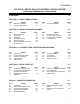
CONTENTS GF-109LN - AERCO KC1000 GAS FIRED LOW NOx BOILER Operating & Maintenance Instructions FOREWORD A SECTION 1 – SAFETY PRECAUTIONS Para. 1.1 1.2 Subject Warnings & Cautions Emergency Shutdown Page 1-1 1-2 1-1 Para. 1.3 Subject Prolonged Shutdown SECTION 2 – INSTALLATION PROCEDURES Para. 2.1 2.2 2.3 2.4 2.5 2.6 Subject Receiving the Unit Unpacking Installation Gas Supply Piping Electrical Supply Mode of Operation and Field Control Wiring Page 2-1 2-1 2-2 2-4 2-6 2-6 Para. 2.7 2.8 2.9 2.
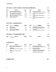
CONTENTS SECTION 6 – SAFETY DEVICE TESTING PROCEDURES Para. 6.1 6.2 6.3 6.4 6.5 6.6 6.7 Subject Testing of Safety Devices Low Gas Pressure Fault Test High Gas Pressure Fault Test Low Water Level Fault Test Water Temperature Fault Test Interlock Fault Tests Flame Fault Test Page 6-1 6-1 6-1 6-2 6-2 6-3 6-3 Para. 6.8 6.9 6.10 6.11 6.
FOREWORD Foreword This system can be operated using natural gas or propane fuel. A simple spring change in the differential regulator and combustion calibration is all that is needed to switch fuels. The AERCO KC Low NOx Boiler is a true industry advance that meets the needs of today's energy and environmental concerns. Designed for application in any closed loop hydronic system, the load tracking capability relates energy input directly to fluctuating system loads through a 11:1 modulating turndown ratio.
SAFETY PRECAUTIONS SECTION 1 -- SAFETY PRECAUTIONS 1.1 WARNINGS & CAUTIONS Installers and operating personnel MUST, at all times, observe all safety regulations. The following warnings and cautions are general and must be given the same attention as specific precautions included in these instructions. In addition to all the requirements included in this AERCO Instruction Manual, the installation of units MUST conform with local building codes, or, in the absence of local codes, ANSI Z223.
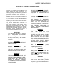
SAFETY PRECAUTIONS 1.2 EMERGENCY SHUTDOWN If overheating occurs or the gas supply fails to shut off, close the manual gas shutoff valve (Figure 1-1) located external to the unit. IMPORTANT The Installer must identify and indicate the location of the emergency shutdown manual gas valve to operating personnel. 1.
INSTALLATION SECTION 2 - INSTALLATION PROCEDURES 2.1. RECEIVING THE UNIT Each KC1000 Boiler is shipped as a single crated unit. The crated shipping weight of the unit is approximately 1500 pounds, and must be moved with the proper rigging equipment for safety and to avoid damages. The unit should be completely inspected for shipping damage and completeness at the time of receipt from the carrier and before the bill of lading is signed.
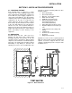
2.3 INSTALLATION The unit must be installed with the prescribed clearances for service as shown in Figure 2.1. The minimum clearance dimensions, required by AERCO, are listed below. Local building codes may require additional clearance and take precedence Minimum clearances required: Sides 24" Front 18" Rear 18" Top 18" All gas piping, water piping, and electrical conduit or cable must be arranged so that they do not interfere with the removal of any cover, or inhibit service or maintenance of the unit.
INSTALLATION 2.3.4 TEMPERATURE/PRESSURE INDICATOR The unit is supplied with one of two styles of Temperature/Pressure Indicators that must be installed in the tapping on the supply flange of the unit (see Figs. 2.5a and 2.5b). A suitable pipe compound should be used sparingly to the threaded connection. Figure 2.3 Supply and Return Location 2.3.3 PRESSURE RELIEF AND DRAIN VALVE INSTALLATION An ASME rated Relief Valve is supplied with each unit.
Figure 2.5b Pressure/Temperature Gauge Installation Figure 2.6 Condensate Drain System Location 2.3.5 CONDENSATE PIPING 2.4. GAS SUPPLY PIPING The KC Boiler is designed to condense. Therefore, the installation site must include suitable provisions for condensate drainage or collection. A stainless steel condensate cup is separately packed within the unit’s shipping container.
INSTALLATION The location of the 1-1/4" inlet gas connection is on the right side of the unit as shown in Figure 2.7. All pipe should be de-burred and internally cleared of any scale or iron chips before installation. No flexible connectors or nonapproved gas fittings should be installed. Piping should be supported from floor or walls only and must not be secured to the unit. A suitable piping compound, approved for use with gas, should be used sparingly.
2.4.2 MANUAL GAS SHUTOFF VALVE A 1-1/4” manual gas shut-off valve is furnished with each unit. The valve should be positioned as shown in Figure 2.7. The manual gas shut-of valve must be installed upstream of the supply regulator in a readily accessible location. 2.4.3 IRI GAS TRAIN KIT The IRI gas train is an optional gas train required in some areas by code or for insurance purposes. The IRI gas train is factory pre-piped and wired. (See Appendix F, Drawing No. SD-A660). 2.
INSTALLATION 2.6.1 CONSTANT SETPOINT MODE The Constant Setpoint Mode is used when it is desired to have a fixed setpoint that does not deviate. No wiring connections other than electrical supply connections are required for this mode. However, if desired, fault monitoring or enable/disable interlock wiring can be utilized (see paragraphs 2.7.9 and 2.7.10). 2.6.2 INDOOR/OUTDOOR RESET MODE This mode of operation increases supply water temperature as outdoor temperatures decrease.
2.6.3 BOILER MANAGEMENT SYSTEM (BMS) MODE NOTE information on wiring the 4 to 20 mA / 1to 5VDC or the 0 to 20 mA / 0 to 5 VDC, see paragraph 2.7.3. 2.6.5 COMBINATION MODE BMS Model 168 can utilize either pulse width modulation (PWM) or RS485 Modbus signaling to the Boiler. BMS II Model 5R5-384 can utilize only RS485 signaling to the Boiler. When using an AERCO Boiler Management System (BMS), the field wiring is connected between the BMS Panel and each Boiler’s I/O Box terminal strip (Figure 2-11).
INSTALLATION shield is to be connected only to the terminals labeled SHEILD in the I/O Box. The sensor end of the shield must be left free and ungrounded. When mounting the sensor, it must be located on the North side of the building where an average outside air temperature is expected. The sensor must be shielded form direct sunlight as well as impingement by the elements. If a shield is used, it must allow for free air circulation. 2.7.
NOTE: Both the Delayed Interlock and Remote Interlock must be in the closed position to allow the unit to fire. 2.7.9.1 REMOTE INTERLOCK IN The remote interlock circuit (REMOTE INTL’K IN) is provided to remotely start (enable) and stop (disable) the Boiler if desired. The circuit is 24 VAC and comes factory pre-wired closed (jumpered). 2.7.9.2 DELAYED INTERLOCK IN The delayed interlock circuit (DELAYED INTL’K IN) is typically used in conjunction with the auxiliary relay described in paragraph 2.8.
INSTALLATION square inches of free area. The free area must take into account restrictions such as louvers and bird screens. 2.10.2 COMBUSTION AIR FROM INSIDE THE BUILDING When combustion air is provided from within the building, it must be supplied through two permanent openings in an interior wall. Each opening must have a free area of not less than one square inch per 1000 BTUH of total input or 1000 square inches of free area. The free area must take into account any restrictions such as louvers.
CONTROL PANEL OPERATING PROCEDURES SECTION 3 - CONTROL PANEL OPERATING PROCEDURES 3.1. INTRODUCTION The information in this Section provides a guide to the operation of the KC1000 Boiler using the Control Panel mounted on the front of the unit. It is imperative that the initial startup of this unit be performed by factory trained personnel. Operation prior to initial startup by factory trained personnel will void the equipment warranty.
CONTROL PANEL OPERATING PROCEDURES Table 3-1. Operating Controls, Indicators and Displays ITEM NO.
CONTROL PANEL OPERATING PROCEDURES Table 3-1. Operating Controls, Indicators and Displays - Continued ITEM NO. 10 (Cont.) CONTROL, INDICATOR OR DISPLAY ▲ (Up) Arrow ▼ (Down) Arrow When in one of the main menu categories (Figure 3-2), pressing this key will select the displayed menu category. If the CHANGE key was pressed and the menu item is flashing, pressing the ▼ (Down) arrow key will increment the selected setting. CHANGE Permits a setting to be changed (edited).
CONTROL PANEL OPERATING PROCEDURES 4. With the desired menu displayed, press the ▲ or ▼ arrow key. The first option in the selected menu will be displayed. 5. Continue to press the ▲ or ▼ arrow key until the desired menu option is displayed. Pressing the ▲arrow key will display the available menu options in the Top-Down sequence. Pressing the ▼ arrow key will display the options in the Bottom-Up sequence. The menu options will wraparound after the first or last available option is reached. 6.
CONTROL PANEL OPERATING PROCEDURES NOTE The Outdoor Temp display item shown with an asterisk in Table 32 will not be displayed unless the Outdoor Sensor function has been enabled in the Configuration Menu (Table 3-4). Table 3-2.
CONTROL PANEL OPERATING PROCEDURES Table 3-4.
CONTROL PANEL OPERATING PROCEDURES 3.7. TUNING MENU The Tuning Menu items in Table 3-5 are Factory set for each individual unit. Do not change these menu entries unless specifically requested to do so by FactoryTrained personnel. Table 3-5. Tuning Menu Menu Item Display Prop Band Integral Gain Derivative Time Reset Defaults? Available Choices or Limits Minimum Maximum 1°F 120°F 0.00 2.00 0.0 min 2.0 min Yes No Are You Sure? Default 70°F 1.00 0.0 min No 3.8.
CONTROL PANEL OPERATING PROCEDURES (a) Blower relay energizes and turns on blower. (b) Air/Fuel Valve rotates to the full-open purge position and closes purge position switch. The dial on the Air/Fuel Valve (Figure 3-4) will read 100 to indicate that the valve is full-open (100%). (c) The FIRE RATE bargraph will show 100%. DIAL (DETAIL “A”) STEPPER MOTOR Figure 3-5. Blower Proof Switch 5.
CONTROL PANEL OPERATING PROCEDURES BURNER BLOWER 8. With the unit firing properly, it will be controlled by the temperature controller circuitry. The FIRE RATE will be continuously displayed on the front panel bargraph. 9. Once the demand for heat has been satisfied, the Control Box will turn off the gas valve. The blower relay will be deactivated and the Air/Fuel Valve will be closed. Standby will be displayed. 3.9.
INITIAL START-UP SECTION 4 - INITIAL START- UP 4.1 INITIAL START- UP REQUIREMENTS The initial start-up of the KC-1000 Low NOx Boiler is comprised of the following steps: • • • • • Installation completed 100% Combustion calibration Proper setting of controls and limits Mode of operation settings (see Section 5) Safety device testing (see Section 6) Installation procedures should be completed 100% before performing initial start-up.
INITIAL START-UP 4.2.4 INSTALLING THE DIFFERENTIAL REGULATOR ADJUSTMENT TOOL 1. First, remove the cap from the differential pressure regulator (see Figure 4.3). 2. Place the gasket from the regulator cap onto the regulator adjustment tool. 3. Prior to Installing the tools on the regulator, pull up the tool's screwdriver blade. Then, thread the tool into the regulator. 4. Engage the tool’s screwdriver blade into the regulator’s adjustment screw slot. Figure 4.1 1/8” Gas Plug Location 4.2.
INITIAL START-UP 1. Open the supply and return valves to the unit and ensure that the system pumps are running. 2. Open the gas supply valve(s) to the unit. 3. If a lockup style regulator is installed as a gas supply regulator, adjust the gas supply until a reading of 12” W.C. static pressure is obtained. 4. Set the ON/OFF switch to the OFF position. Turn on AC power to the unit. The display will show LOSS OF POWER and the time and date. 5. Set the unit to the Manual Mode by pressing the AUTO/MAN switch.
INITIAL START-UP 18. Oxygen levels at the 16% firing rate should be as shown in Table 2 (page 4-5). Also, ensure that the CO and NOx readings do not exceed the values shown. No adjustment should be necessary. Contact the Factory if the oxygen, CO or NOx levels are not within the specified ranges. NOTE: At a 100% firing rate, the KC1000 will not operate reliably at inlet air temperatures below 55°F if the Cold Air Damper (P/N 99026) is not installed. See paragraphs 2.10.2 and 2.10.3. 19.
INITIAL START-UP Table 1 Combustion Oxygen Levels for a 30% Firing Rate Inlet Air Temp -25°F -10°F 0°F 10°F 25°F 40°F 55°F 70°F 85°F 100°F Oxygen (±0.2%) 7.8% 7.5% 7.4% 7.2% 6.9% 6.5% 6.4% 6.2% 5.9% 5.7% Carbon Monoxide <100 ppm <100 ppm <100 ppm <100 ppm <100 ppm <100 ppm <100 ppm <100 ppm <100 ppm <100 ppm *NOx <30 ppm <30 ppm <30 ppm <30 ppm <30 ppm <30 ppm <30 ppm <30 ppm <30 ppm N/A * NOx readings corrected to 3% oxygen.
INITIAL START-UP 1. Open the supply and return valves to the unit and ensure that the system pumps are running. 2. Open the gas supply valve(s) to the unit. 3. If a lockup style regulator is installed as a gas supply regulator, adjust the gas supply until a reading of 11” W.C. static pressure is obtained. 4. Set the ON/OFF switch to the OFF position. Turn on AC power to the unit. The display will show LOSS OF POWER and the time and date. 5. Set the unit to the Manual Mode by pressing the AUTO/MAN switch.
INITIAL START-UP the CO and NOx readings do not exceed the values shown. Firmly tighten the inlet air shutter locking nuts when finished. 17. Once the oxygen level is within the specified range at 30%, change the firing rate to 16%. 18. Oxygen levels at the 16% firing rate should be as shown in Table 2. Also, ensure that the CO and NOx readings do not exceed the values shown. No adjustment should be necessary. Contact the Factory if the oxygen, CO or NOx levels are not within the specified ranges.
INITIAL START-UP 4.6 OVER TEMPERATURE LIMIT SWITCH ADJUSTMENTS There are two Over-Temperature Limit switches that turn off the unit when the outlet water temperature becomes too hot. The lower overtemperature limit switch is adjustable and should be adjusted 20° to 40°F above the operating header temperature. The upper over-temperature limit switch is a manual reset device and is not adjustable. It will shut the unit off if the water temperature reaches 240°F. DO NOT attempt to adjust its setpoint.
MODE OF OPERATION SECTION 5 - MODE OF OPERATION 5.1 INTRODUCTION The following paragraphs provide detailed descriptions of the six different modes of operation for the KC1000 Boiler. Each unit is shipped from the factory tested and configured for the ordered mode of operation. All temperature related parameters are at factory defaults and work well in most applications. However, it may be necessary to change certain parameters to customize the unit to the system.
MODE OF OPERATION 11. Press the CHANGE key. begin to flash. The display will 12. Use the ▲ and ▼ arrow keys to select the reset ratio determined in step 5. 13. Press ENTER to save the change. Refer to paragraph 3.3 for detailed instructions on menu changing. 5.3 CONSTANT SETPOINT MODE The Constant Setpoint mode is used when a fixed header temperature is desired.
MODE OF OPERATION If the Network setting is selected for RS485 Modbus operation, a valid Comm Address must be entered in the Setup Menu. Refer to Modbus Communication Manual GF-114 for additional information. While it is possible to change the settings of temperature related functions, the unit is factory preset with settings that work well in most applications. It is suggested that an AERCO representative be contacted, prior to changing any temperature related function settings.
MODE OF OPERATION If the Network setting is selected for RS485 Modbus operation, a valid Comm Address must be entered in the Setup Menu. Refer to Modbus Communication Manual GF-114 for additional information. 5.5.1 DIRECT DRIVE FIELD WIRING The only wiring connections necessary for Direct Drive mode are connection of the remote signal leads from the source to the unit’s I/O Box. For either a 4-20mA/0-5V or a 0-20mA/0-5V setting, the connections are made at the ANALOG IN terminals in the I/O Box.
MODE OF OPERATION 5.7 COMBINATION CONTROL SYSTEM (CCS) NOTE Only BMS Model 168 can be utilized for the Combination Mode, not the BMS II (Model 5R5-384). A Combination Control System (CCS) is one that uses multiple boilers to cover both space-heating and domestic hot water needs. An AERCO Boiler Management System (BMS) Model 168 and a Combination Control Panel (CCP) are necessary to configure this system.
SAFETY DEVICE TESTING SECTION 6-SAFETY DEVICE TESTING PROCEDURES 6.1 TESTING OF SAFETY DEVICES Periodic testing of all controls and safety devices is required to insure that they are operating as designed. Precautions must be taken while tests are being performed to protect against bodily injury and property damage. 6. Open the gas supply to the unit and press the CLEAR button on the Control Box. 7. The unit should restart.
SAFETY DEVICE TESTING low water cutoff. Press the CLEAR button to reset the FAULT LED and clear the error message. 11. Set the ON/OFF switch to the ON position. The unit is now ready for operation. 6.5 WATER TEMPERATURE FAULT TEST 1. In the normal operating mode, allow the unit to stabilize at its setpoint. 2. Lower the adjustable temperature limit switch setting to match the outlet water temperature. (See Fig. 6.3). Figure 6.2 High Gas Pressure Switch 6.4 LOW WATER LEVEL FAULT TEST 1.
SAFETY DEVICE TESTING 6.6 INTERLOCK TESTS The unit is equipped with two interlock circuits called the Remote Interlock and the Delayed Interlock. Terminal connections for these circuits are located in the I/O Box and are labeled REMOTE INTL’K IN and DELAYED INTL’K IN. These circuits can shut down the unit in the event that an interlock is opened. These interlocks are shipped from the factory jumped (closed).
SAFETY DEVICE TESTING 6.8 AIR FLOW FAULT TEST 1. Start the unit in manual mode and set the fire rate between 25% and 30%. 2. Once the unit has proved flame, remove either wire #154 or #155 from the blower proof switch (see Fig. 6.5) located on the air/fuel valve. 3. The unit should shut down and display AIRFLOW FAULT DURING RUN. 4. Replace the wire previously removed from the blower-proof switch and depress the CLEAR button. The unit should restart.
SAFETY DEVICE TESTING 6.10 PURGE SWITCH OPEN DURING PURGE 6.11 IGNITION SWITCH OPEN DURING IGNITION 1. Set the unit’s ON/OFF switch to the OFF position. Place the unit in manual mode and set the fire rate between 25% and 30% 1. Set the unit’s ON/OFF switch to the OFF position. Place the unit in manual mode and set the fire rate between 25% and 30%. 2. Remove the air/fuel valve cover by rotating the cover counterclockwise to unlock it and then pulling it towards you. See Fig. 6.7. 2.
SAFETY DEVICE TESTING 6.12 SAFETY PRESSURE RELIEF VALVE TEST Test the unit’s Safety Pressure Relief Valve in accordance with ASME Boiler and Pressure Vessel Code, Section VI.
MAINTENANCE SECTION 7 - MAINTENANCE 7.1 MAINTENANCE SCHEDULE The unit requires regular routine maintenance to keep up efficiency and reliability. For best operation and life of the unit, the routine maintenance procedures listed in Table 1 should be performed within the specified time periods. Table 1 Maintenance Schedule Para 7.2 7.3 7.4 7.5 7.6 Item Spark Igniter Flame Detector Combustion Cal. Testing of Safety Devices *Manifold & Tubes 6 Mos. Inspect 12 Mos.
MAINTENANCE 7.3 FLAME DETECTOR The flame detector assembly is located in the body of the burner (Figure 7.1). The flame detector may be HOT. Allow the unit to cool sufficiently before removing the flame detector. To inspect or replace the flame detector: The following replacement parts will be required for reassembly after inspection: GP-122537 GP-18900 Combustion Chamber Gasket Manifold to Tubesheet Gasket Burner Head/Plate Gasket Burner Plate/Shell Gasket Combustion Chamber Liner 1.
MAINTENANCE 7. Loosen the 1/4” NPT union on the low NOx staged ignition assembly (Figure 7.3). 8. Disconnect the staged ignition assembly 1/8” elbow from the 3” long NPT nipple at the bottom of the burner shell. Figure 7.4 Exhaust Sensor Connector Location 16. Disconnect the air/fuel valve 12-pin connector from the KC wiring harness. 17. Disconnect wires #24 and #17 from the blower proof switch (Figure 7.5). Figure 7.3 Burner Disassembly Diagram 9. Remove the 3” long NPT nipple and 1/4” O.D.
MAINTENANCE 19. Using an 11/16” wrench, loosen the compression fittings on the feedback tube between the air/fuel valve and the differential pressure regulator. Remove the feedback tube (Figure 7.7). NOTE: The combustion chamber liner should be installed prior to reinstalling the exhaust manifold 20. Using two 9/16” wrenches, remove the two 3/8-16 hex nuts and bolts securing the air/fuel valve to the differential pressure regulator (Figure 7.7). 21.
MAINTENANCE 1/4" PLUG RELIEF VALVE REDUCING BUSHING HOT WATER SUPPLY (OUTLET) HOT WATER RETURN (INLET) REDUCING BUSHING DRAIN VALVE Figure 7.9 Heat Exchanger Supply and Return Locations 4. Remove the 2 ½ inch plug located in the shell at the rear of the unit (Figure 7.10). 5. Remove the relief valve, drain valve (Figure 7.9) and any reducing bushings. 6. Perform the inspection. Reassemble the unit once the inspection is completed. 7. Open the supply and return valves and reconnect AC power to the unit.
TROUBLESHOOTING Chapter 8- TROUBLESHOOTING GUIDE 8.1 INTRODUCTION This troubleshooting guide is intended to aid service/maintenance personnel in isolating the cause of a fault in a KC1000 Boiler. The troubleshooting procedures contained herein are presented in tabular form on the following pages. These tables are comprised of three columns labeled: Fault Indication, Probable Cause and Corrective Action. The numbered items in the Probable Cause and Corrective Action columns correspond to each other.
TROUBLESHOOTING TABLE 8-1. BOILER TROUBLESHOOTING FAULT INDICATION PROBABLE CAUSES CORRECTIVE ACTION AIRFLOW FAULT DURING IGNITION 1. Blower stopped running due to thermal or current overload 2. Blocked Blower inlet or inlet ductwork 1. Check combustion blower for signs of excessive heat or high current drain that may trip thermal or current overload devices. 2. Inspect the inlet to the combustion blower including any ductwork leading up to the combustion blower for signs of blockage. 3.
TROUBLESHOOTING TABLE 8-1. BOILER TROUBLESHOOTING – Continued FAULT INDICATION DELAYED INTERLOCK OPEN DIRECT DRIVE SIGNAL FAULT FLAME LOSS DURING IGN PROBABLE CAUSES 1. Delayed Interlock Jumper not installed or removed. 2. Device proving switch hooked to interlocks is not closed 1. Direct drive signal is not present: Not yet installed. Wrong polarity. Signal defective at source. Broken or loose wiring. 2. Signal is not isolated (floating). 3.
TROUBLESHOOTING TABLE 8-1. BOILER TROUBLESHOOTING – Continued FAULT INDICATION FLAME LOSS DURING RUN PROBABLE CAUSES 1. Worn Flame Detector or cracked ceramic. 1. Remove and inspect the Flame Detector for signs of wear or cracked ceramic. Replace if necessary. 2. Defective Differential Regulator. 2. Check gas pressure readings using a gauge or manometer into and out of the Air/Fuel Valve to ensure that the gas pressure into and out of the valve is correct. 3. Check combustion calibration.
TROUBLESHOOTING TABLE 8-1. BOILER TROUBLESHOOTING – Continued FAULT INDICATION HIGH WATER TEMP SWITCH OPEN PROBABLE CAUSES 1. Faulty Water temperature switch. 2. Incorrect PID settings. 3. Faulty shell temperature sensor. 4. Unit in Manual mode 5. Unit setpoint is greater than Over Temperature Switch setpoint. 6. Boiler Management System PID or other settings not correctly setup. 7. No interlock to boiler or BMS to disable boiler(s) in event that system pumps have failed. 8.
TROUBLESHOOTING TABLE 8-1. BOILER TROUBLESHOOTING – Continued FAULT INDICATION IGN SWTCH CLOSED DURING PURGE PROBABLE CAUSES 1. Air/Fuel Valve not rotating 2. Defective or shorted switch 3. Switch wired incorrectly 4. Defective Power Supply Board or fuse 5. Defective IGST Board IGN SWTCH OPEN DURING IGNITION 1. Air/Fuel Valve not rotating to ignition position. 2. Defective ignition switch 3. Defective Power Supply Board or fuse 4. Defective IGST Board INTERLOCK OPEN 1.
TROUBLESHOOTING TABLE 8-1. BOILER TROUBLESHOOTING – Continued FAULT INDICATION LINE VOLTAGE OUT OF PHASE LOW GAS PRESSURE PROBABLE CAUSES 1. Line and Neutral switched in AC Power Box. 2. Incorrect power supply transformer wiring. 1. Incorrect supply gas pressure. 2. Defective or incorrectly sized Gas Supply Regulator. 3. Defective Low Pressure Gas Switch LOW WATER LEVEL 1. Insufficient water level in system 2. Defective water level circuitry. 3. Defective water level probe.
TROUBLESHOOTING TABLE 8-1. BOILER TROUBLESHOOTING – Continued FAULT INDICATION PROBABLE CAUSES continued 5. Defective IGST Board PRG SWTCH OPEN DURING PURGE 1. Defective purge switch. 2. No voltage present at switch. 3. Switch wired incorrectly. 4. Defective Power Supply Board or fuse 5. Defective IGST Board OUTDOOR TEMP SENSOR FAULT REMOTE SETPT SIGNAL FAULT RESIDUAL FLAME 1. Loose or broken wiring. 2. Defective Sensor. 3. Incorrect Sensor. 1. Remote setpoint signal not present: Not yet installed.
TROUBLESHOOTING TABLE 8-1. BOILER TROUBLESHOOTING – Continued FAULT INDICATION (continued) SSOV FAULT DURING PURGE SSOV FAULT DURING RUN SSOV RELAY FAILURE SSOV SWITCH OPEN PROBABLE CAUSES 2. Defective Flame Detecto See SSOV SWITCH OPEN 2. Replace Flame Detector. 1. SSOV switch closed for 15 seconds during run. 1. SSOV relay failed on board. 1. Replace or adjust microswitch in SSOV actuator. If fault persists, replace actuator. 1. Press CLEAR button and restart unit.
APPENDIX A BOILER MENU ITEM DESCRIPTIONS MENU LEVEL & OPTION DESCRIPTION OPERATING MENU Active Setpoint This is the setpoint temperature to which the control is operating when operating in the Constant Setpoint, Remote Setpoint or Outdoor Reset Mode. When in the Constant Setpoint Mode, this value is equal to the Internal Setpoint setting in the Configuration Menu. When in the Remote Setpoint Mode, this value is the setpoint equivalent to the remote analog signal supplied to the unit.
APPENDIX A BOILER MENU ITEM DESCRIPTIONS - Continued MENU LEVEL & OPTION DESCRIPTION SETUP MENU Password Allows password to be entered. Once the valid password (159) is entered, options in the Setup, Configuration and Tuning Menus can be modified. Language English Only Time Displays time from 12:00am to 11:59pm. Date Displays dates from 01/01/00 to 12/31/99 Unit of Temp Permits selection of temperature displays in degrees Fahrenheit (°F) or degrees Celsius (°C). Default is °F.
APPENDIX A BOILER MENU ITEM DESCRIPTIONS - Continued MENU LEVEL & OPTION DESCRIPTION Reset Ratio Permits setting of Reset Ratio when operating boiler in the Outdoor Reset Mode. Reset Ratio is adjustable from 0.1 to 9.9. Default is 1.2. Outdoor Sensor Allows outdoor sensor function to be enabled or disabled. Default is Disabled. System Start Tmp If outdoor sensor is enabled in the Configuration Menu, this menu item allows the system start temperature to be set from 30°F to 100°F. Default is 60°F.
APPENDIX A BOILER MENU ITEM DESCRIPTIONS - Continued MENU LEVEL & OPTION DESCRIPTION Setpt Limiting Allows Setpoint Limiting to be enabled or disabled. Default is disabled. Setpt Limit Band If Setpoint Limiting is enabled, this menu item allows the Setpt Limit Band to be set from 0°F to 10°F. Default is 5°F. TUNING MENU A-4 Prop Band Generates a fire rate based on the error that exists between the setpoint temperature and the actual outlet temperature.
APPENDIX B STARTUP, STATUS AND FAULT MESSAGES STARTUP AND STATUS MESSAGES MESSAGE DISABLED HH:MM pm MM/DD/YY STANDBY DEMAND DELAY XX sec PURGING XX sec IGNITION TRIAL XX sec FLAME PROVEN WARMUP XX sec WAIT DESCRIPTION Displayed if ON/OFF switch is set to OFF. The display also shows the time and date that the unit was disabled. Displayed when ON/OFF switch is in the ON position, but there is no demand for heat. The time and date are also displayed. Displayed if Demand Delay is active.
APPENDIX B FAULT MESSAGES FAULT MESSAGE HIGH WATER TEMP SWITCH OPEN LOW WATER LEVEL LOW GAS PRESSURE HIGH GAS PRESSURE INTERLOCK OPEN DELAYED INTERLOCK OPEN AIRFLOW FAULT DURING PURGE PRG SWTCH OPEN DURING PURGE IGN SWTCH OPEN DURING IGNITION IGN SWTCH CLOSED DURING PURGE PRG SWTCH CLOSED DURING IGNITION AIRFLOW FAULT DURING IGN AIRFLOW FAULT DURING RUN SSOV SWITCH OPEN SSOV FAULT DURING PURGE SSOV FAULT DURING IGN SSOV FAULT DURING RUN SSOV RELAY FAILURE FLAME LOSS DURING IGN FLAME LOSS DURING RUN HIGH EX
APPENDIX B FAULT MESSAGES - Continued FAULT MESSAGE RESIDUAL FLAME HEAT DEMAND FAILURE IGN BOARD COMM FAULT DIRECT DRIVE SIGNAL FAULT REMOTE SETPT SIGNAL FAULT OUTDOOR TEMP SENSOR FAULT OUTLET TEMP SENSOR FAULT FFWD TEMP SENSOR FAULT HIGH WATER TEMPERATURE LINE VOLTAGE OUT OF PHASE STEPPER MOTOR FAILURE NETWORK COMM FAULT FAULT DESCRIPTION The Flame signal was seen for more than 60 seconds during standby. The Heat Demand Relays on the Ignition board failed to activate when commanded.
APPENDIX C Temperature Sensor Resistance Chart (Balco) C-1
APPENDIX D INDOOR/OUTDOOR RESET RATIO CHARTS Header Temperature for a Building Reference Temperature of 50F RESET RATIO Air Temp 0.6 0.8 1.0 1.2 1.4 1.6 1.8 2.0 2.2 2.
APPENDIX D Header Temperature for a Building Reference Temperature of 65F RESET RATIO Air Temp 0.6 0.8 1.0 1.2 1.4 1.6 1.8 2.0 2.2 2.
APPENDIX D Header Temperature for a Building Reference Temperature of 75F RESET RATIO Air Temp 0.6 0.8 1.0 1.2 1.4 1.6 1.8 2.0 2.2 2.
APPENDIX D Header Temperature for a Building Reference Temperature of 90F RESET RATIO Air Temp 0.6 0.8 1.0 1.2 1.4 1.6 1.8 2.0 2.2 2.
APPENDIX E BOILER DEFAULT SETTINGS MENU & OPTION FACTORY DEFAULT Setup Menu Password 0 Language English Unit of Temp Comm Address Baud Rate Fahrenheit 0 9600 Configuration Menu Internal Setpt 130°F Unit Type Boiler Unit Size 1.0 MBTU Boiler Mode Remote Signal (If Mode = Remote Setpoint, Direct Drive or Combination) Constant Setpoint 4 – 20 mA /1-5V Bldg Ref Temp (If Boiler Mode = Outdoor Reset) 70°F Reset Ratio (If Boiler Mode = Outdoor Reset) 1.
APPENDIX F F-1
APPENDIX F F-2
APPENDIX F F-3
APPENDIX F F-4
APPENDIX F F-5
APPENDIX F F-6
APPENDIX G G-1
APPENDIX G G-2
APPENDIX G G-3
APPENDIX H H-1
ECO 2 3 4 6 REVISIONS SEE SHEET ONE 237 7 236 5 235 8 238 240 241 242 243 244 245 9 10 11 12 13 14 15 239 THESE DRAWINGS AND/OR SPECIFICATIONS ARE THE PROPERTY OF AERCO INTERNATIONAL, INC. THEY ARE ISSUED IN STRICT CONFIDENCE AND SHALL NOT BE REPRODUCED, COPIED, OR USED AS THE BASIS FOR MANUFACTURE OR SALE OF APPARATUS WITHOUT PERMISSION OF THE OWNER. REV J1 1 234 8 233 13 232 DATE 247 16 1 246 2 BY 4 251 5 252 6 253 8 7 254 CK'D J3 B ORIGINAL DWG.
APPENDIX I KC1000 CONTROL PANEL EXPLODED VIEW I-1
APPENDIX I KC1000 CONTROL PANEL REAR VIEW I-2
APPENDIX J KC1000 LOW NOx DUAL-FUEL SWITCH-OVER INSTRUCTIONS The KC1000 Low NOx Boiler is shipped from the factory configured for either natural gas or propane operation, as specified on the Sales Order. However, if required, the unit’s operating configuration can be easily switched from natural gas to propane (or vice-versa) by performing a simple change to the spring contained in the unit’s differential regulator.
INTERNATIONAL, INC. STANDARD WARRANTY: Gas-Fired Hydronic Boiler Model KC-1000GWB & PWB (Propane) PRESSURE VESSEL: 10 YEARS NON-PRORATED The shell shall carry a non-prorated 10 year guarantee from shipment against leakage due to thermal shock, mechanical defects or workmanship. The shell will not be covered for waterside corrosion.
INTERNATIONAL, INC. STANDARD WARRANTY: Gas-Fired Hydronic Boiler Model KC-1000GWB & PWB (Propane) CONDITIONS OF WARRANTY Should an AERCO gas-fired (natural gas or propane only) water heater or hydronic boiler fail for any of the above reasons within the specified time period from the date of original shipment(s), AERCO shall at its option modify, repair or exchange the defective item.