RECON Water Heaters Installation, Operation & Maintenance Manual USER MANUAL Natural Gas Modulating, Condensing Water Heater Models: RECON 500 RECON 1000 Installation, Operation and Maintenance RECON Series Gas-Fired Water Heaters Applicable to Serial Numbers: G-14-2390 and above Other documents for this product include: GF-5030 GF-5050 GF-5060 Gas Supply Guide Venting Guide Elect. Power Guide Creation Date: 10/28/2014 OMM-0103_0A GF-147 AERCO International, Inc. 100 Oritani Dr.
RECON Water Heaters Installation, Operation & Maintenance Manual --DISCLAIMER The information contained in this manual is subject to change without notice from AERCO International, Inc. AERCO makes no warranty of any kind with respect to this material, including, but not limited to, implied warranties of merchantability and fitness for a particular application.
RECON Water Heaters Installation, Operation & Maintenance Manual TABLE OF CONTENTS FOREWORD.......................................................................................................................................... 7 CHAPTER 1: SAFETY PRECAUTIONS ............................................................................................ 13 1.1 WARNINGS & CAUTIONS ................................................................................................... 13 1.2 EMERGENCY SHUTDOWN ...
RECON Water Heaters Installation, Operation & Maintenance Manual 2.15 DUCTED COMBUSTION .................................................................................................... 37 CHAPTER 3: OPERATION ................................................................................................................. 39 3.1 INTRODUCTION .................................................................................................................. 39 3.2 CONTROL PANEL DESCRIPTION ................
RECON Water Heaters Installation, Operation & Maintenance Manual 5.12 SAFETY PRESSURE RELIEF VALVE TEST ..................................................................... 78 CHAPTER 6: MAINTENANCE ........................................................................................................... 79 6.1 MAINTENANCE SCHEDULE ............................................................................................... 79 6.2 IGNITER-INJECTOR .......................................................
RECON Water Heaters Installation, Operation & Maintenance Manual 8.10 TROUBLESHOOTING ...................................................................................................... 130 8.11 SEQUENCING VALVE DESCRIPTION & OPERATION .................................................. 130 8.11.1 Sequencing Valve Description .................................................................................................... 130 8.11.2 Sequencing Valve Operating Characteristics............................
RECON Water Heaters Installation, Operation & Maintenance Manual FORWARD FOREWORD The AERCO RECON Series Potable Water Heaters are modulating units which represent a true industry advance that meets the needs of today's energy efficiency and environmental concerns. Designed for use in any domestic water heating system, each RECON model provides precisely-controlled potable water within ±2°F of setpoint, for up to 50% load changes.
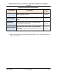
RECON Water Heaters Installation, Operation & Maintenance Manual FORWARD RECON Potable Water Heater Models Description Shipping Weight RECON500 RECON Potable Water Heater, 500,000 BTU/HR Input, Natural Gas FM Gas Train 875 lbs. RECON500DBB RECON Potable Water Heater, 500,000 BTU/HR Input, Natural Gas, Double Block & Bleed (Formerly IRI) Gas Train 875 lbs. RECON1000 RECON Potable Water Heater, 1,000,000 BTU/HR Input, Natural, FM Gas Train 910 lbs.
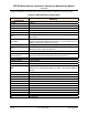
RECON Water Heaters Installation, Operation & Maintenance Manual FORWARD Phrases, abbreviations and acronyms used in this manual are listed in the following Table: Phrases, Abbreviations and Acronyms Phrase, Abbreviation or Acronym A (Amp) ADDR AGND ALRM ASME AUX BAS Baud Rate BLDG (Bldg) BTU CCP C-More Controller (or Control Box) CO COMM (Comm) Cal. CNTL DBB DIP EMS FM GND HDR HX Hz I.D.
RECON Water Heaters Installation, Operation & Maintenance Manual FORWARD Phrases, Abbreviations and Acronyms – Continued Phrase, Abbreviation or Acronym I/O Box IP IRI ISO LED LN MA (mA) MAX (Max) MIN (Min) Modbus® NC (N.C.) NO (N.O.) NOx NPT O2 O.D. PMC Board PPM PTP REF (Ref) RES.
RECON Water Heaters Installation, Operation & Maintenance Manual FORWARD Phrases, Abbreviations and Acronyms – Continued Phrase, Abbreviation or Acronym Terminating Resistor VAC VDC VFD W W.C.
RECON Water Heaters Installation, Operation & Maintenance Manual FORWARD (This Page Is Intentionally Blank) Page 12 of 178 PRI: 10/28/2014 AERCO International, Inc. 100 Oritani Dr.
RECON Water Heaters Installation, Operation & Maintenance Manual CHAPTER 1: – SAFETY PRECAUTIONS CHAPTER 1: SAFETY PRECAUTIONS 1.1 WARNINGS & CAUTIONS Installers and operating personnel MUST, at all times, observe all safety regulations. The following warnings and cautions are general and must be given the same attention as specific precautions included in these instructions.
RECON Water Heaters Installation, Operation & Maintenance Manual CHAPTER 1: – SAFETY PRECAUTIONS --CAUTION! – Many of the soaps used for gas pipe leak testing are corrosive to metals. The piping must be rinsed thoroughly with clean water after leak checks have been completed. DO NOT use this heater if any part has been under water. Call a qualified service technician to inspect and replace any part that has been under water. 1.
RECON Water Heaters Installation, Operation & Maintenance Manual CHAPTER 1: – SAFETY PRECAUTIONS IMPORTANT – FOR MASSACHUSETTS INSTALLATIONS Water heater Installations within the Commonwealth of Massachusetts must conform to the following requirements: Heater must be installed by a plumber or a gas fitter who is licensed within the Commonwealth of Massachusetts. Prior to unit operation, the complete gas train and all connections must be leak tested using a non-corrosive soap.
RECON Water Heaters Installation, Operation & Maintenance Manual CHAPTER 1: – SAFETY PRECAUTIONS (b) EXEMPTIONS: The following equipment is exempt from 248 CMR 5.08(2)(a)1 through 4: 1. The equipment listed in Chapter 10 entitled "Equipment Not Required To Be Vented" in the most current edition of NFPA 54 as adopted by the Board; and 2.
RECON Water Heaters Installation, Operation & Maintenance Manual CHAPTER 2 – INSTALLATION CHAPTER 2: INSTALLATION 2.1 INTRODUCTION This Chapter provides the descriptions and procedures necessary to unpack, inspect and install AERCO RECON Water Heater Models RECON500 and RECON1000. 2.2 RECEIVING THE UNIT Each RECON Water Heating System is shipped as a single crated unit. The shipping weight is approximately 1000 pounds.
RECON Water Heaters Installation, Operation & Maintenance Manual CHAPTER 2 – INSTALLATION 2.4 SITE PREPARATION Ensure that the site selected for installation of the RECON Water Heater includes: Access to AC Input Power at 120 VAC, Single-Phase, 60 Hz @ 20 Amps. Access to Natural Gas line at a minimum pressure of 4 inches W.C. with the unit operating at maximum capacity. 2.4.1 Installation Clearances All RECON Models are packaged in enclosures having identical exterior dimensions.
RECON Water Heaters Installation, Operation & Maintenance Manual CHAPTER 2 – INSTALLATION FOR MASSACHUSETTS ONLY For Massachusetts installations, the unit must be installed by a plumber or gas-fitter who is licensed within the Commonwealth of Massachusetts. In addition, the installation must comply with all requirements specified in Chapter 1 (Safety Precautions), pages 13 and 14. 2.4.2 Setting the Unit The unit must be installed on a 4 inch to 6 inch housekeeping pad to ensure proper condensate drainage.
RECON Water Heaters Installation, Operation & Maintenance Manual CHAPTER 2 – INSTALLATION 2.5 WATER INLET AND OUTLET PIPING The locations of the 2" NPT cold water inlet and hot water outlet piping connections are shown in Figure 2-3a. Flow rates through the unit are limited to 50 gpm continuous. Shut-off valves and union connections must be installed in the inlet and outlet lines for maintenance. The use of dielectric unions is recommended.
RECON Water Heaters Installation, Operation & Maintenance Manual CHAPTER 2 – INSTALLATION P&T RELIEF VALVE HOT WATER OUTLET 2” NPT EXHAUST MANIFOLD GAS INLET 1-1/4" Figure 2-3b: Inlets and Outlets –Covers Removed OMM-0103_0A GF-147 AERCO International, Inc. 100 Oritani Dr.
RECON Water Heaters Installation, Operation & Maintenance Manual CHAPTER 2 – INSTALLATION 2.5.1 WHM Actuator-Controlled Ball Valve Installation If the RECON Water Heater was ordered for use with an isolation valve, it will be packed separately within the shipping container. If installation is required, proceed as follows: WHM Ball Valve Installation 1. Remove the ball valve from its stowed location within the shipping container. 2. Attached the valve to the cold water inlet (Figure 2.
RECON Water Heaters Installation, Operation & Maintenance Manual CHAPTER 2 – INSTALLATION 2.6 INSTALLING THE TEST HOSE BIB AND DRAIN VALVE A Test Hose Bib must be installed upstream of the hot water outlet shut off valve, This is required for startup and testing (see Figure 2-5 A). The pipe diameter should be a minimum of 3/4". The Test Hose Bib cannot be omitted.
RECON Water Heaters Installation, Operation & Maintenance Manual CHAPTER 2 – INSTALLATION 2.7 SYSTEM RECIRCULATION LOOP The RECON Recirculation Loop Assembly is located inside the unit enclosure on the right side of the unit. Remove the upper and lower right side panels to access this assembly. Refer to Figure 2-6. This assembly contains a recirculator pump which connects between the upper hot water outlet and lower cold water inlet of the unit’s heat exchanger.
RECON Water Heaters Installation, Operation & Maintenance Manual CHAPTER 2 – INSTALLATION NOTE The maximum working pressure for installations within the Province of Alberta is 87 psig. Therefore, a pressure & temperature relief valve with a setting of 75 psig/190°F is supplied with Alberta shipments. 2.8 PRESSURE & TEMPERATURE RELIEF VALVE INSTALLATION An ASME rated Pressure & Temperature (P&T) Relief Valve is supplied with each RECON Water Heater.
RECON Water Heaters Installation, Operation & Maintenance Manual CHAPTER 2 – INSTALLATION 2.9 CONDENSATE DRAIN & PIPING The RECON Water Heater is designed to condense water vapor from the flue products. Therefore, the installation must have provisions for suitable condensate drainage or collection. The condensate drain port is located on the exhaust manifold at the rear of the unit (Figure 2-8). This drain port must be connected to the Condensate Trap (part no.
RECON Water Heaters Installation, Operation & Maintenance Manual CHAPTER 2 – INSTALLATION Condensate Trap Installation 1. Connect the condensate trap inlet to the exhaust manifold drain connection using the appropriate piping components (nipples, reducers, elbows, etc.) for the heater installation site. An example is shown in Figure 2-9. 2. At the condensate trap outlet, install a 3/4” NPT nipple. 3. Connect a length of 1” I.D. polypropylene hose to the trap outlet and secure with a hose clamp. 4.
RECON Water Heaters Installation, Operation & Maintenance Manual CHAPTER 2 – INSTALLATION NOTE As a general guideline, AERCO recommends use of its Neutralizer Kit to raise the pH level of the condensate prior to drainage. At a minimum, the installation must be designed in accordance with local codes that specify acceptable pH limits. 2.
RECON Water Heaters Installation, Operation & Maintenance Manual CHAPTER 2 – INSTALLATION 2.10.2 Manual Gas Shutoff Valve A manual shut-off valve must be installed in the gas supply line upstream of the Heater as shown in Figure 2-10. The maximum allowable gas pressure to the unit is 14” W.C. 2.10.3 External Gas Supply Regulator An external gas pressure regulator is required on the gas inlet piping under most conditions (see sections 2.10.3.1 and 2.10.3.2, below).
RECON Water Heaters Installation, Operation & Maintenance Manual CHAPTER 2 – INSTALLATION NOTE It is the responsibility of the customer to source and purchase the appropriate gas regulator as described above. However, AERCO offers for sale an appropriate regulator, which may be ordered at the time of unit purchase or separately. Contact AERCO for more information. 2.
RECON Water Heaters Installation, Operation & Maintenance Manual CHAPTER 2 – INSTALLATION Each unit must be connected to a dedicated electrical circuit. NO OTHER DEVICES SHOULD BE ON THE SAME ELECTRICAL CIRCUIT AS THE HEATER. A double-pole switch must be installed on the electrical supply line in an easily accessible location to quickly and safely disconnect electrical service. DO NOT attach the switch to sheet metal enclosures of the unit.
RECON Water Heaters Installation, Operation & Maintenance Manual CHAPTER 2 – INSTALLATION Figure 2-13: Input/Output (I/O) Box – Front View, Box Cover Removed Since identical I/O Boxes are used with both AERCO gas-fired boilers and water heaters, some of the input and output connections apply only to boilers while others are common to both boilers and heaters. These I/O Box connections are noted in the sections below. NOTE Use Figure 2-14 to determine the functions of the I/O PCB connections.
RECON Water Heaters Installation, Operation & Maintenance Manual CHAPTER 2 – INSTALLATION Figure 2-14: I/O Box Terminal Strips 2.12.1 OUTDOOR AIR IN Terminal The OUTDOOR AIR IN and AIR SENSOR COMMON terminals are not applicable to this unit. 2.12.2 AIR TEMPERATURE SENSOR Terminals The COMBUSTION AIR and AIR SENSOR COMMON terminals are not applicable to this unit. 2.12.3 O2 SENSOR Terminals The O2 SENSOR (–) and O2 SENSOR (+) terminals are not currently used in this unit. 2.12.
RECON Water Heaters Installation, Operation & Maintenance Manual CHAPTER 2 – INSTALLATION Either a 4 to 20 mA /1 to 5 VDC or a 0 to 20 mA/ 0 to 5 VDC signal may be used to vary the setpoint or air/fuel valve position. The factory default setting is for 4 to 20 mA / 1 to 5 VDC, however this may be changed to 0 to 20 mA / 0 to 5 VDC using the Configuration Menu described in Chapter 3.
RECON Water Heaters Installation, Operation & Maintenance Manual CHAPTER 2 – INSTALLATION 2.12.9 RS485 COMM Terminals The RS485 communication terminals (+, GND, & -) are used when the RECON Water Heaters are being controlled by an Energy Management System (EMS) or the C-More Water Heater Management (WHM) system using Modbus (RS485) communication. The WHM software required to control up to 8 AERCO RECON Water Heaters is included in the C-More Control System used with each RECON unit. 2.12.
RECON Water Heaters Installation, Operation & Maintenance Manual CHAPTER 2 – INSTALLATION 2.12.14 AUX RELAY Terminals Each unit is equipped with a single pole double throw (SPDT) auxiliary relay that is energized when there is a demand for heat and de-energized after the demand for heat is satisfied. The relay is provided for the control of auxiliary equipment, such as pumps and louvers, or can be used as a unit status indictor (firing or not firing). Its contacts are rated for 120 VAC @ 5 amps.
RECON Water Heaters Installation, Operation & Maintenance Manual CHAPTER 2 – INSTALLATION The more common methods of combustion air supply are outlined in the following sections. For combustion air supply from ducting, consult the Innovation and RECON Venting and Combustion Air Guide, GF-5050. 2.14.1 Combustion From Outside the Building Air supplied from outside the building must be provided through two permanent openings.
RECON Water Heaters Installation, Operation & Maintenance Manual CHAPTER 2 – INSTALLATION (This Page Is Intentionally Blank) Page 38 of 178 PRI: 10/28/2014 AERCO International, Inc. 100 Oritani Dr.
RECON Water Heaters Installation, Operation & Maintenance Manual CHAPTER 3 – OPERATION CHAPTER 3: OPERATION 3.1 INTRODUCTION The information in this Chapter provides a guide to the operation of the RECON Water Heater using the Control Panel mounted on the front of the unit. It is imperative that the initial startup of this unit be performed by factory trained personnel. Operation prior to initial startup by factory trained personnel will void the equipment warranty.
RECON Water Heaters Installation, Operation & Maintenance Manual CHAPTER 3 – OPERATION 3.2 CONTROL PANEL DESCRIPTION The RECON Control Panel shown in Figure 3-1 contains all of the controls, indicators and displays necessary to operate, adjust and troubleshoot the RECON Water Heater. These operating controls, indicators and displays are listed and described in Table 3-1. Additional information on these items is provided in the individual operating procedures provided in this Chapter.
RECON Water Heaters Installation, Operation & Maintenance Manual CHAPTER 3 – OPERATION 9 10 LOW WATER LEVEL TEST/RESET Switches: Allows operator to test operation of the water level monitor. Pressing TEST opens the water level probe circuit and simulates a Low Water Level alarm. Pressing RESET resets the water level monitor circuit. Pressing the CLEAR key (item 6) resets the display.
RECON Water Heaters Installation, Operation & Maintenance Manual CHAPTER 3 – OPERATION 3.3 CONTROL PANEL MENUS The Control Panel incorporates an extensive menu structure which permits the operator to set up, and configure the unit. The menu structure consists of five major menu categories which are applicable to this manual. These categories are shown in Figure 3-2. Each of the menus shown, contain options which permit operating parameters to be viewed or changed.
RECON Water Heaters Installation, Operation & Maintenance Manual CHAPTER 3 – OPERATION NOTE The WHM menu is only displayed when the unit type in the Configuration Menu is set to RECON WH. Figure 3-2. Menu Structure NOTE The following sections provide brief descriptions of the options contained in each menu. Refer to Appendix A for detailed descriptions of each menu option. Refer to Appendix B for listings and descriptions of displayed startup, status and error messages.
RECON Water Heaters Installation, Operation & Maintenance Manual CHAPTER 3 – OPERATION 3.4 OPERATING MENU The Operating Menu displays a number of key operating parameters for the unit, as listed in Table 3-2. This menu is “Read-Only” and does not allow personnel to change or adjust any displayed items. It can therefore be viewed at any time without entering a password. Pressing the ▲ arrow key to display the menu items in the order listed (Top-Down).
RECON Water Heaters Installation, Operation & Maintenance Manual CHAPTER 3 – OPERATION 3.5 SETUP MENU The Setup Menu (Table 3-3) permits the operator to enter the unit password (159) which is required to change the menu options. To prevent unauthorized use, the password will time-out after 1 hour, requiring the correct password to be reentered when required. In addition, the Setup Menu is also used to enter date and time, and units of temperature measurements.
RECON Water Heaters Installation, Operation & Maintenance Manual CHAPTER 3 – OPERATION Table 3-4: Configuration Menu Menu Item Display 1 2 3 4 5 6 7 8 9 10 11 12 13 14 15 16 17 18 19 20 21 22 23 24 25 26 Internal Setpt Unit Type Unit Size Fuel Type Water Heater Mode Remote Signal (If Mode = Remote Setpoint, Direct Drive or Combination) Outdoor Sensor System Start Tmp (If Outdoor Sensor = Enabled) Setpt Lo Limit Setpt Hi Limit Temp Hi Limit Max Valve Position Pump Delay Timer Aux Start On Dly Failsafe Mod
RECON Water Heaters Installation, Operation & Maintenance Manual CHAPTER 3 – OPERATION 3.7 TUNING MENU The Tuning Menu items in Table 3-5 are Factory set for each individual unit. Do not change these menu entries unless specifically requested to do so by Factory-Trained personnel. A full description of each item appears in Table A-4 of Appendix A – Recon Menu Item Descriptions.
RECON Water Heaters Installation, Operation & Maintenance Manual CHAPTER 3 – OPERATION Menu Item Display Available Choices or Limits Minimum Maximum Default 24 Temp Gov 25 GOV Limit-5 0 100 30 26 GOV Limit-7 0 100 20 27 GOV Limit-10 0 100 15 28 GOV Limit-12 0 100 10 29 GOV Limit-15 0 100 5 30 PID Output 0% 100% Read Only Value 31 P Output 0% 100% Read Only Value 32 I Output 0% 100% Read Only Value 33 D Output 0% 100% Read Only Value 34 Reset Defaults Yes
RECON Water Heaters Installation, Operation & Maintenance Manual CHAPTER 3 – OPERATION Menu Item Display Available Choices or Limits Default Minimum Maximum 60% 100% 70% 13 4-20mA Purge Pct 14 PWM In Adj -5.0% 5.0% 0.0% 15 Analog In Adj -5.0% 5.0% 0.0% 16 -5.0% 5.0% 0.0% 17 Flow In Adj Supply Gas Pressure In Adj -5.0% 5.0% 0.0% 18 Gas Plate dp In Adj -5.0% 5.0% 0.0% 19 mA Out Adj -1.0 mA 1.0 mA 0.
RECON Water Heaters Installation, Operation & Maintenance Manual CHAPTER 3 – OPERATION 3.9 START SEQUENCE When the Control Box ON/OFF switch is set to the ON position, it checks all pre-purge safety switches to ensure they are closed.
RECON Water Heaters Installation, Operation & Maintenance Manual CHAPTER 3 – OPERATION Start Sequence 1. The DEMAND LED status indicator will light. 2. The unit checks to ensure that the Proof of Closure (POC) switch in the downstream Safety Shut-Off Valve (SSOV) is closed. See Figure 3-3 for SSOV location. TO AIR/FUEL VALVE MANUAL SHUTOFF VALVE SSOV GAS INLET Figure 3-3: Gas Train and SSOV Location (RECON 1000 Shown) 3.
RECON Water Heaters Installation, Operation & Maintenance Manual CHAPTER 3 – OPERATION Start Sequence – Continued 4. Next, the blower proof switch on the Air/Fuel Valve (Figure 3-5) closes. The display will show Purging and indicate the elapsed time of the purge cycle in seconds. BLOWER PROOF SWITCH STEPPER MOTOR TRANSPARENT COVER BLOCKED INLET SWITCH AIR IN TO BLOWER AIR/FUEL VALVE GAS IN Figure 3-5: Blower Proof Switch 5.
RECON Water Heaters Installation, Operation & Maintenance Manual CHAPTER 3 – OPERATION Start Sequence – Continued STEPPER MOTOR AIR IN IGNITION VALVE POSITION DIAL AT 25% to 35% TO BLOWER Figure 3-6: Air/Fuel Valve In Ignition Position 6. Up to 4 seconds will be allowed for ignition to be detected. The igniter relay will be turned off one second after flame is detected. 7. After 2 seconds of continuous flame, Flame Proven will be displayed and the flame strength will be indicated.
RECON Water Heaters Installation, Operation & Maintenance Manual CHAPTER 3 – OPERATION 3.10 START/STOP LEVELS The start and stop levels are the Air/Fuel Valve positions (% open) that start and stop the unit, based on load. These levels are Factory preset as follows: Start Level Stop Level RECON 500 28% 16% RECON 1000 25% 20% Normally, these settings should not require adjustment. Note that the energy input is not linearly related to the Air/Fuel Valve position.
RECON Water Heaters Installation, Operation & Maintenance Manual CHAPTER 4 – INITIAL START-UP CHAPTER 4: INITIAL START-UP 4.
RECON Water Heaters Installation, Operation & Maintenance Manual CHAPTER 4 – INITIAL START-UP 4.2.1 Required Tools & Instrumentation The following tools and instrumentation are necessary to perform combustion calibration of the unit: Digital Combustion Analyzer: Oxygen accuracy to ± 0.4%; Carbon Monoxide (CO) and Nitrogen Oxide (NOx) resolution to 1PPM. 16 inch W.C. manometer or equivalent gauge and plastic tubing.
RECON Water Heaters Installation, Operation & Maintenance Manual CHAPTER 4 – INITIAL START-UP Installing the Gas Supply Manometer – Continued MANUAL SHUTOFF VALVE TO AIR/FUEL VALVE 1/4" NPT PLUG (Install manometer here) LOW GAS PRESSURE SWITCH HIGH GAS PRESSURE SWITCH LEAK DETECTION BALL VALVE GAS INLET SSOV Figure 4-1: Manometer Installation Location into 1/4” NPT Plug OMM-0103_0A GF-147 AERCO International, Inc. 100 Oritani Dr.
RECON Water Heaters Installation, Operation & Maintenance Manual CHAPTER 4 – INITIAL START-UP 4.2.3 Accessing the Analyzer Probe Port The unit contains a 1/8” NPT port at the rear of the exhaust manifold. This port is located above the condensate drain connection as shown in Figure 4-2. Prepare the port for the combustion analyzer probe as follows: Accessing Analyzer Probe Port 1. Refer to Figure 4-2 and remove the 1/8” NPT plug from the rear of the exhaust manifold. 2.
RECON Water Heaters Installation, Operation & Maintenance Manual CHAPTER 4 – INITIAL START-UP Connecting a Multimeter to the Flame Detector 1. Refer to Figure 4-3 and remove the right side panel from the unit to access the flame detector. 2. Disconnect the flame detector wire lead 135 from the detector and connect the multimeter in series with the wire lead using alligator clips as shown in Figure 4-3. 3. Ensure that the multimeter is set to the µA scale.
RECON Water Heaters Installation, Operation & Maintenance Manual CHAPTER 4 – INITIAL START-UP 4.3 NATURAL GAS COMBUSTION CALIBRATION The RECON Heater is combustion calibrated at the factory prior to shipping. However, recalibration is necessary as part of initial start-up due to changes in the local altitude, gas BTU content, gas supply piping and supply regulators. Start-Up & Registration Test Data sheets are shipped with each unit.
RECON Water Heaters Installation, Operation & Maintenance Manual CHAPTER 4 – INITIAL START-UP NATURAL GAS Combustion Calibration – Continued BRASS HEX HEAD CAP (Remove to access gas pressure adjustment screw) Figure 4-4: Gas Pressure Adjustment Screw Location 13. Replace the brass cap on the SSOV gas pressure adjustment if it was previously removed. 14.
RECON Water Heaters Installation, Operation & Maintenance Manual CHAPTER 4 – INITIAL START-UP NATURAL GAS Combustion Calibration – Continued NOTE If NOx readings exceed the target values shown (<20 ppm), increase the O2 level up to 25% higher than the listed calibration range shown in the table. Record the increased O2 value on the Combustion Calibration sheet. Valve Position 80% Combustion Calibration Readings Nitrogen Carbon Oxygen (O2) % Oxide (NOx) Monoxide (CO) 6.5% ± 0.
RECON Water Heaters Installation, Operation & Maintenance Manual CHAPTER 4 – INITIAL START-UP Reassembly after Combustion Calibration 1. Set the ON/OFF switch in the OFF position. 2. Disconnect AC power from the unit. 3. Shut off the gas supply to the unit. 4. Remove the manometer and barbed fittings and reinstall the NPT plug using a suitable pipe thread compound. 5. Remove the combustion analyzer probe from the 1/4” vent hole in the exhaust manifold. Replace the 1/8” NPT plug in the manifold. 6.
RECON Water Heaters Installation, Operation & Maintenance Manual CHAPTER 4 – INITIAL START-UP 4.4.1 Setting the Outlet Water Temperature Setpoint The setpoint temperature of the unit may be changed using the following steps. However, once a setpoint has been changed, recalibration may be necessary. To adjust the unit’s setpoint, proceed as follows: Setting Outlet Water Temperature Setpoint 1. Press the MENU key until Configuration Menu is displayed. 2.
RECON Water Heaters Installation, Operation & Maintenance Manual CHAPTER 4 – INITIAL START-UP 4.4.3 Maximum Load Adjustment Check the temperature control at maximum load as follows: Maximum Load Adjustment 1. While monitoring the VALVE POSITION bar-graph, create a maximum load on the system that will yield a steady valve position between 80% and 90%. NOTE It may be necessary to open the outlet valve if it was closed during minimum load adjustment to obtain a sufficient flow rate for maximum adjustment.
RECON Water Heaters Installation, Operation & Maintenance Manual CHAPTER 4 – INITIAL START-UP 4.5 OVER-TEMPERATURE LIMIT SWITCHES The unit contains both automatic and manual reset over-temperature limit switches. These switches are mounted as shown in Figure 4-5. The manual reset switch is not adjustable and is permanently fixed at 190°F. This switch will shut down and lock out the heater if the water temperature exceeds 190°F.
RECON Water Heaters Installation, Operation & Maintenance Manual CHAPTER 5 – SAFETY DEVICE TESTING CHAPTER 5: SAFETY DEVICE TESTING 5.1 INTRODUCTION Periodic safety device testing is required to ensure that the control system and safety devices are operating properly. The heater control system comprehensively monitors all combustionrelated safety devices before, during and after the start sequence. The following tests check to ensure that the system is operating as designed.
RECON Water Heaters Installation, Operation & Maintenance Manual CHAPTER 5 – SAFETY DEVICE TESTING 5.2 LOW GAS PRESSURE FAULT TEST Refer to Figure 5-1 and ensure that the leak detection ball valve located at the high gas pressure switch is closed. Low Gas Pressure Fault Test 1. Remove the 1/4“ plug from the ball valve at the low gas pressure switch, shown in the lower portion of Figure 5-1, and then install an NPT to barbed fitting in its place. 2. Install a 0 – 16“ W.C. manometer or a W.C.
RECON Water Heaters Installation, Operation & Maintenance Manual CHAPTER 5 – SAFETY DEVICE TESTING 5.3 HIGH GAS PRESSURE FAULT TEST To simulate a high gas pressure fault, refer to Figure 5-1 and proceed as follows: High Gas Pressure Fault 1. Remove the 1/4“ plug from the leak detection ball valve at the high pressure switch, shown in Figure 5-1, and then install an NPT to barbed fitting in its place. 2. Install a 0 – 16” W.C. manometer (or W.C. gauge) where the 1/4” plug was removed. 3.
RECON Water Heaters Installation, Operation & Maintenance Manual CHAPTER 5 – SAFETY DEVICE TESTING Low Water Level Fault Test – Continued 11. Press the CLEAR button to reset the FAULT LED and clear the displayed error message. 12. Set the ON/OFF switch to the ON position. The unit is now ready for operation. 5.5 WATER TEMPERATURE FAULT TEST A high water temperature fault is simulated by adjusting the automatic over-temperature switch.
RECON Water Heaters Installation, Operation & Maintenance Manual CHAPTER 5 – SAFETY DEVICE TESTING MANUAL RESET (NON-ADJUSTABLE) OVER-TEMPERATURE LIMIT SWITCH AUTOMATIC RESET (ADJUSTABLE) TEMPERATURE OVER- LIMIT SWITCH Figure 5-2: Temperature Limit Switch Setting 5.6 INTERLOCK TESTS The unit is equipped with two interlock circuits called the Remote Interlock and Delayed Interlock.
RECON Water Heaters Installation, Operation & Maintenance Manual CHAPTER 5 – SAFETY DEVICE TESTING 5.6.2 Delayed Interlock Test Delayed Interlock Test 1. Remove the cover from the I/O Box and locate the DELAYED INTL’K IN terminals (see Figure 2-12). 2. Start the unit in the Manual Mode at a valve position between 25% and 30%. 3. If there is a jumper across the DELAYED INTL’K IN terminals, remove one side of the jumper.
RECON Water Heaters Installation, Operation & Maintenance Manual CHAPTER 5 – SAFETY DEVICE TESTING Flame Fault Tests – Continued 11. Open the valve previously closed in step 8. 12. Press the CLEAR button. The unit should restart and fire. MANUAL SHUTOFF VALVE Figure 5-3: Manual Gas Shut-Off Valve Location (RECON 1000 Shown) 5.8 AIR FLOW FAULT TESTS These tests check the operation of the Blower Proof Switch and Blocked Inlet Switch shown in Figure 5-4. Air Flow Fault Tests 1.
RECON Water Heaters Installation, Operation & Maintenance Manual CHAPTER 5 – SAFETY DEVICE TESTING Air Flow Fault Tests – Continued 6. Once the unit has proved flame, turn off the blower by going to the Configuration Menu, Analog Output menu item and select OFF. 7. The Blower Proof Switch will open and the blower should stop. The unit should shut down and display AIRFLOW FAULT DURING RUN. 8. Go to the Configuration Menu, Analog Output item and select VALVE POSITION 0-10v. 9. Press the CLEAR button.
RECON Water Heaters Installation, Operation & Maintenance Manual CHAPTER 5 – SAFETY DEVICE TESTING AIR INLET EXHAUST MANIFOLD GAS INLET 1-1/4" Figure 5-5: Rear View of Water Heater Indicating the Air Inlet 5.9 SSOV PROOF OF CLOSURE SWITCH The SSOV shown in Figure 5-1 contains the proof of closure switch. The proof of closure switch circuit is checked as follows: SSOV Proof of Closure Switch 1. Set the unit’s ON/OFF switch to the OFF position. 2.
RECON Water Heaters Installation, Operation & Maintenance Manual CHAPTER 5 – SAFETY DEVICE TESTING SSOV SSOV ACTUATOR COVER ACTUATOR COVER SCREW Figure 5-6: SSOV Actuator Cover Location 5.10 PURGE SWITCH OPEN DURING PURGE The Purge Switch (and Ignition Switch) is located on the Air/Fuel Valve. To check the switch, proceed as follows: Purge Switch Open During Purge 1. Set the unit’s ON/OFF switch to the OFF position. Place the unit in manual mode and set the valve position between 25% and 30%. 2.
RECON Water Heaters Installation, Operation & Maintenance Manual CHAPTER 5 – SAFETY DEVICE TESTING 5.11 IGNITION SWITCH OPEN DURING IGNITION The Ignition Switch (and the Purge Switch) is located on the Air/Fuel Valve. To check the switch, proceed as follows: Ignition Switch Open During Ignition 1. Set the unit’s ON/OFF switch to the OFF position. 2. Place the unit in Manual Mode and set the valve position between 25% and 30%. 3.
RECON Water Heaters Installation, Operation & Maintenance Manual CHAPTER 5 – SAFETY DEVICE TESTING VALVE POSITION DIAL TO BLOWER Ignition Position Switch AIR IN 171 169 170 AIR/FUEL VALVE SWITCH WIRING BREAKOUT Purge Position Switch 172 Figure 5-8: Air/Fuel Valve Purge and Ignition Switch Locations 5.12 SAFETY PRESSURE RELIEF VALVE TEST Test the safety Pressure & Temperature (P&T) Relief Valve in accordance with ASME Pressure Vessel Code, Section VI.
RECON Water Heaters Installation, Operation & Maintenance Manual CHAPTER 6 – MAINTENANCE CHAPTER 6: MAINTENANCE 6.1 MAINTENANCE SCHEDULE The RECON Water Heater requires regular routine maintenance to ensure continued reliable operation throughout the service life of the unit. For optimum operation, AERCO recommends that the following routine maintenance procedures be performed in the time periods specified in Table 6-1.
RECON Water Heaters Installation, Operation & Maintenance Manual CHAPTER 6 – MAINTENANCE 6.2 IGNITER-INJECTOR The ignition system’s igniter-injector (kit P/N 58023) is located on the burner plate on the underside of the heat exchanger. In addition to providing the ignition spark required to light the burner, the igniter-injector also contains a gas injector tube which connects to the ignition assembly.
RECON Water Heaters Installation, Operation & Maintenance Manual CHAPTER 6 – MAINTENANCE Igniter-Injector Inspection and Replacement – Continued 7. Prior to reinstalling the igniter-injector, apply a high temperature, conductive, anti-seize compound to the threads.
RECON Water Heaters Installation, Operation & Maintenance Manual CHAPTER 6 – MAINTENANCE 6.3 FLAME DETECTOR Flame detector (kit P/N 24356-2) is used on ALL RECON Water Heater Models. The flame detector is located on the flange of the blower-side intake manifold as shown in Figure 6-1. The flame detector may be hot. Allow the unit to cool sufficiently before removing the flame detector. To inspect or replace the flame detector: Flame Detector Inspection/Replacement 1.
RECON Water Heaters Installation, Operation & Maintenance Manual CHAPTER 6 – MAINTENANCE 6.6 FIRESIDE INSPECTION The recommended method for fireside inspection is to remove the observation port (Figure 6.1) and use a borescope inserted into the combustion chamber to inspect the burner and combustion chamber areas.
RECON Water Heaters Installation, Operation & Maintenance Manual CHAPTER 6 – MAINTENANCE Fireside Inspection – Continued HEAT EXCHANGER IGNITER-INJECTOR EXHAUST SENSOR CAP SCREWS 1/4-20 x 7/8” LG.
RECON Water Heaters Installation, Operation & Maintenance Manual CHAPTER 6 – MAINTENANCE Fireside Inspection – Continued EXHAUST MANIFOLD CONDENSATE SHIELD BLOWER MANIFOLD GASKET (P/N 81136) BURNER FLANGE GASKET (P/N GP-18899) SHIELD GASKET (P/N 81197) 10-22 x 3/8” BURNER MOUNTING SCREWS BURNER MOUNTING PLATE BURNER FLANGE GASKET (P/N GP-18899) 5/16-18 HEX NUTS (6 EACH) INTAKE MANIFOLD NOTE Support the intake manifold as it is carefully lowered from the blower plenum and heat exchanger.
RECON Water Heaters Installation, Operation & Maintenance Manual CHAPTER 6 – MAINTENANCE Fireside Inspection – Continued EXHAUST MANIFOLD BURNER FLANGE GASKET (P/N GP-18899) BURNER ASSEMBLY BURNER CONDENSATE SHIELD SHIELD GASKET (P/N 81197) BURNER FLANGE GASKET (P/N GP-18899) INTAKE MANIFOLD BURNER, INTAKE AND EXHAUST MANIFOLDS – EXPLODED Figure 6-6.
RECON Water Heaters Installation, Operation & Maintenance Manual CHAPTER 6 – MAINTENANCE 6.7 WATERSIDE INSPECTION The waterside of the heating surfaces and anode may be inspected by removal of the top heater head (see Figure 6-7).
RECON Water Heaters Installation, Operation & Maintenance Manual CHAPTER 6 – MAINTENANCE LIFTING RING 5/8-11 HEX NUT UPPER HEAD LINER (P/N 123077) WASHER UPPER HEAD HEAD RELEASE GASKET (P/N GP-18556) 5/8-11 X 3-3/4” STUD HEAD GASKET (P/N GP-18532) SHELL FLANGE WASHER HEAT EXCHANGER SHELL 5/8-11 HEX NUT Figure 6-7: Heat Exchanger Head Configuration 6.7.
RECON Water Heaters Installation, Operation & Maintenance Manual CHAPTER 6 – MAINTENANCE 1/4-20 HEX HEAD SEAL BOLTS (4) ANODE BLOCK ANODE BLOCK ANODE MOUNTING BRACKET Figure 6-8: Anode Assembly and Combustion Chamber Head 6.8 HEAT EXCHANGER CLEANING AERCO recommends that the heat exchanger of the unit be cleaned annually to maintain maximum heat transfer efficiencies using a solution of HydroSkrub and water. HydroSkrub is distributed by AERCO International, Inc.
RECON Water Heaters Installation, Operation & Maintenance Manual CHAPTER 6 – MAINTENANCE 6.8.1 Pumping System Set-Up A sample pumping set-up diagram is shown in Figure 6-9 A and 6-9 B. As this diagram shows, heat exchanger cleaning is accomplished by pumping the HydroSkrub solution from a large circulation bucket to the heat exchanger drain valve, through the heat exchanger and then out through the output connection of the heater. Set up the pumping system as follows: Pumping System Set-Up Instructions 1.
RECON Water Heaters Installation, Operation & Maintenance Manual CHAPTER 6 – MAINTENANCE HOSE FROM CIRCULATION BUCKET DRAIN VALVE PARTIAL RIGHT SIDE VIEW Figure 6-9 B: Connecting to Internal Drain Valve 6.8.2 Cleaning Procedure Cleaning Procedure 1. Slowly add the following amount of HydroSkrub solution to the circulation bucket. RECON 500 RECON 1000 13 Gallons 16 Gallons 2. Open the drain valve, outlet hose connection valve and turn on the pump.
RECON Water Heaters Installation, Operation & Maintenance Manual CHAPTER 6 – MAINTENANCE Cleaning Procedure – Continued 9. HydroSkrub is biodegradable, and in most instances may be purged down sewers. Check with local authorities before disposing of any complex compositions. 10. Turn off water, shut off the pump and immediately close discharge valves to prevent backflow. 11. Completely drain pump bucket. Disconnect the hoses from equipment and thoroughly rinse the bucket, pump, and associated hoses used.
RECON Water Heaters Installation, Operation & Maintenance Manual CHAPTER 6 – MAINTENANCE Condensate Trap Inspection and Cleaning – Continued 5. Thoroughly clean the trap, float and orifice gasket (if so equipped). Also inspect the drain piping for blockage. If the trap cannot be thoroughly cleaned, replace the trap. 6. After the above items have been thoroughly cleaned and inspected, replace the float in the condensate trap and replace the trap cover. 7.
RECON Water Heaters Installation, Operation & Maintenance Manual CHAPTER 6 – MAINTENANCE Air Filter Replacement – Continued 5. Each replacement air filter is equipped with its own clamp. Therefore, simply install the replacement air filter on inlet flange of the air fuel valve and tighten the clamp with a flat-tip screwdriver or 5/16” nut driver. 6. Replace the side panels on the unit and return heater to service use.
RECON Water Heaters Installation, Operation & Maintenance Manual CHAPTER 6 – MAINTENANCE LWCO Probe Plastic Acorn Nut Capacitor Assembly (Covered By Large Shrink Tubing) Connector (to Shell Harness) FRONT VIEW, TOP COVERS REMOVED LWCO Probe Terminal Figure 6-12: LWCO Probe Location 6.11.1 Low Water Cutoff (LWCO) - Capacitor Electrical Short Test This test determines if there is an electrical short between the LWCO capacitor and the heat exchanger.
RECON Water Heaters Installation, Operation & Maintenance Manual CHAPTER 6 – MAINTENANCE LWCO Capacitor Electrical Short Test – Continued P3 EXT. SENSOR/COMM HARNESS CONNECTOR (24 PIN) TO INPUT/OUTPUT (I/O) BOX SENSOR HARNESS CONNECTOR (7 PIN) P1 A/F VALVE HARNESS CONNECTOR (16 PIN) P2 GAS TRAIN HARNESS CONNECTOR (9 PIN) P5 SHELL HARNESS CONNECTOR (19 PIN) Unplug Shell Harness Cable from P5 Connector P4 INTERLOCK HARNESS CONNECTOR (16 PIN) TO INPUT/OUTPUT (I/O) BOX P6 2.
RECON Water Heaters Installation, Operation & Maintenance Manual CHAPTER 6 – MAINTENANCE LWCO Capacitor Integrity Test – Continued 5. Confirm that the ohmmeter does NOT read a short. NOTE If the ohmmeter reads a short, the capacitor assembly needs to be replaced. Refer to document TID-0094, provided with the 24-month maintenance kit, for LWCO replacement instructions. 6. Remove both ohmmeter probes and reconnect the Shell Harness connector to the P5 connector on the rear of the C-More controller. 6.11.
RECON Water Heaters Installation, Operation & Maintenance Manual CHAPTER 6 – MAINTENANCE 6.12 SHUTTING THE WATER HEATER DOWN FOR AN EXTENDED PERIOD OF TIME If the unit is to be taken out of service for an extended period of time (one year or more), complete the following procedures. Extended Period Shut-Down 1. Set ON/OFF switch on the front panel to the OFF position to shut down the heater’s operating controls. 2. Disconnect AC power from the unit. 3.
RECON Water Heaters Installation, Operation & Maintenance Manual CHAPTER 7 – TROUBLESHOOTING GUIDE CHAPTER 7: TROUBLESHOOTING GUIDE 7.1 INTRODUCTION This troubleshooting guide is intended to aid service/maintenance personnel in isolating the cause of a fault in a RECON Water Heater. The troubleshooting procedures contained herein are presented in tabular form on the following pages. These tables are comprised of three columns labeled: Fault Indication, Probable Cause and Corrective Action.
RECON Water Heaters Installation, Operation & Maintenance Manual CHAPTER 7 – TROUBLESHOOTING GUIDE (This Page Is Intentionally Blank) Page 100 of 178 PRI: 10/28/2014 AERCO International, Inc. 100 Oritani Dr.
RECON Water Heaters Installation, Operation & Maintenance Manual CHAPTER 7 – TROUBLESHOOTING GUIDE TABLE 7-1: WATER HEATER TROUBLESHOOTING FAULT INDICATION PROBABLE CAUSES CORRECTIVE ACTION 1. Blower stopped running due to 1. Check combustion blower for signs of excessive heat or high thermal or current overload 2. Blocked Blower inlet or inlet ductwork 2. Inspect the inlet to the combustion blower including any ductwork current drain that may trip thermal or current overload devices.
RECON Water Heaters Installation, Operation & Maintenance Manual CHAPTER 7 – TROUBLESHOOTING GUIDE TABLE 7-1: WATER HEATER TROUBLESHOOTING – Continued FAULT INDICATION PROBABLE CAUSES 1. Blower not running or running too slow 2. Defective Air Flow Switch 3. Blocked Air flow Switch AIRFLOW FAULT DURING PURGE 4. Blocked Blower inlet or inlet ductwork. 5. No voltage to switch from control box. 6. PROBABLE CAUSES from 3 to 12 for AIRFLOW FAULT DURING IGNITION applies for this fault 1.
RECON Water Heaters Installation, Operation & Maintenance Manual CHAPTER 7 – TROUBLESHOOTING GUIDE TABLE 7-1: WATER HEATER TROUBLESHOOTING – Continued FAULT INDICATION DELAYED INTERLOCK OPEN PROBABLE CAUSES 1. Delayed Interlock Jumper not 1. Check for a jumper properly installed across the delayed installed or removed. 2. Device proving switch hooked to interlocks is not closed 1. Burner Ground Screw not installed interlock terminals in the I/O box. 2.
RECON Water Heaters Installation, Operation & Maintenance Manual CHAPTER 7 – TROUBLESHOOTING GUIDE TABLE 7-1: WATER HEATER TROUBLESHOOTING – Continued FAULT INDICATION FLAME LOSS DURING RUN PROBABLE CAUSES 1. Worn Flame Detector or cracked 1. Remove and inspect the Flame Detector for signs of wear ceramic. 2. Defective Regulator. or cracked ceramic. Replace if necessary. 2.
RECON Water Heaters Installation, Operation & Maintenance Manual CHAPTER 7 – TROUBLESHOOTING GUIDE TABLE 7-1: WATER HEATER TROUBLESHOOTING – Continued FAULT INDICATION PROBABLE CAUSES 1. Faulty Water temperature switch. 2. Incorrect PID settings. 3. Faulty shell temperature sensor. HIGH WATER TEMP SWITCH OPEN 4. Unit in Manual mode 5. Unit setpoint is greater than Over Temperature Switch setpoint. 6. System flow rate changes are occurring faster than units can respond. 1.
RECON Water Heaters Installation, Operation & Maintenance Manual CHAPTER 7 – TROUBLESHOOTING GUIDE TABLE 7-1: WATER HEATER TROUBLESHOOTING – Continued FAULT INDICATION PROBABLE CAUSES 3. Switch wired incorrectly (continued) 4. Defective Power Supply Board or fuse 5. Defective IGST Board 1. Air/Fuel Valve not rotating to ignition position. IGN SWTCH OPEN DURING IGNITION 2. Defective ignition switch 3. Defective Power Supply Board or fuse 4. Defective IGST Board INTERLOCK OPEN CORRECTIVE ACTION 3.
RECON Water Heaters Installation, Operation & Maintenance Manual CHAPTER 7 – TROUBLESHOOTING GUIDE TABLE 7-1: WATER HEATER TROUBLESHOOTING – Continued FAULT INDICATION PROBABLE CAUSES CORRECTIVE ACTION 1. Line and Neutral switched in AC 1. Check hot and neutral in AC Power Box to ensure they are not Power Box. reversed. 2. Incorrect power supply transformer 2. Check transformer wiring, in AC Power Box, against the power wiring. box transformer wiring diagram to ensure it is wired correctly. 1.
RECON Water Heaters Installation, Operation & Maintenance Manual CHAPTER 7 – TROUBLESHOOTING GUIDE TABLE 7-1: WATER HEATER TROUBLESHOOTING – Continued FAULT INDICATION (continued) PRG SWTCH OPEN DURING PURGE OUTDOOR TEMP SENSOR FAULT RECIRC PUMP FAILURE REMOTE SETPT SIGNAL FAULT PROBABLE CAUSES CORRECTIVE ACTION 3. Switch wired incorrectly. 3. If the switch is wired correctly, replace the switch. 4. Defective Power Supply Board or fuse 4. Check DS1 & DS2 LEDs on Power Supply Board.
RECON Water Heaters Installation, Operation & Maintenance Manual CHAPTER 7 – TROUBLESHOOTING GUIDE TABLE 7-1: WATER HEATER TROUBLESHOOTING – Continued FAULT INDICATION PROBABLE CAUSES 1. SSOV not fully closed. RESIDUAL FLAME 2. Defective Flame Detector SSOV FAULT DURING PURGE SSOV FAULT DURING RUN SSOV SWITCH OPEN 1. Check open/close indicator window of Safety Shut-Off Valve (SSOV) and ensure that the SSOV is fully closed. If not fully closed, replace the valve and or actuator.
RECON Water Heaters Installation, Operation & Maintenance Manual CHAPTER 7 – TROUBLESHOOTING GUIDE TABLE 7-1: WATER HEATER TROUBLESHOOTING – Continued PROBABLE CAUSES FAULT INDICATION STEPPER MOTOR FAILURE 1. Air/Fuel Valve out of calibration. 2. Air/Fuel Valve unplugged. 3. Loose wiring connection to the stepper motor. 4. Defective Air/Fuel Valve stepper motor. 5. Defective Power Supply Board or fuse 6. Defective IGST Board WARNING EXHAUST TEMP HIGH (Flashing WARNING) 1.
RECON Water Heaters Installation, Operation & Maintenance Manual CHAPTER 7 – TROUBLESHOOTING GUIDE 7.2 ADDITIONAL FAULTS WITHOUT SPECIFIC FAULT MESSAGES Refer to Table 7-2 to troubleshoot faults which may occur without a specific fault message being displayed. TABLE 7-2: WATER HEATER TROUBLESHOOTING WITH NO FAULT MESSAGE DISPLAYED OBSERVED INCIDENT Fluctuating Gas Pressure Air/Fuel Valve “hunting” at the 80% Valve Position OMM-0103_0A GF-147 PROBABLE CAUSES 1.
RECON Water Heaters Installation, Operation & Maintenance Manual CHAPTER 7 – TROUBLESHOOTING GUIDE (This Page Is Intentionally Blank) Page 112 of 178 PRI: 10/28/2014 AERCO International, Inc. 100 Oritani Dr.
RECON Water Heaters Installation, Operation & Maintenance Manual CHAPTER 7 – TROUBLESHOOTING GUIDE MANUAL SHUTOFF VALVE TO AIR/FUEL VALVE LEAK DETECTION BALL VALVE LOW GAS PRESSURE SWITCH LEAK DETECTION BALL VALVE HIGH GAS PRESSURE SWITCH GAS INLET SSOV Figure 7-1: Gas Train Component Locations (RECON 1000 Shown) FLAME DETECTOR MOUNTING STAND-OFFS FLAME DETECTOR GASKET CLOCKING WASHERS (1 TO 3 EA.
RECON Water Heaters Installation, Operation & Maintenance Manual CHAPTER 7 – TROUBLESHOOTING GUIDE DAMPING ORFICE SSOV ACTUATOR COVER ACTUATOR COVER SCREW BRASS HEX HEAD CAP (Remove to access gas pressure adjustment screw) OPEN/CLOSED TRANSPARENT INDICATOR WINDOW Figure 7-3. SSOV Actuator with Gas Pressure Adjustment & Damping Orifice Page 114 of 178 PRI: 10/28/2014 AERCO International, Inc. 100 Oritani Dr.
RECON Water Heaters Installation, Operation & Maintenance Manual CHAPTER 8 – WATER HEATER MANAGEMENT CHAPTER 8: WATER HEATER MANAGEMENT NOTE Some of the descriptions and procedures provided in this Chapter may duplicate information provided in previous Chapters of this manual. This is being done to minimize referencing back to these descriptions and procedures and organize all WHM related information into a single Chapter.
RECON Water Heaters Installation, Operation & Maintenance Manual CHAPTER 8 – WATER HEATER MANAGEMENT 8.2 WHM PRINCIPLES OF OPERATION The WHM system communicates with the plant water heaters via a RS485 network utilizing Modbus RTU protocol (8 bit, 9600 baud, no parity). All Modbus networks are implemented using a Master/Slave scenario where only one device, the Master, can initiate a communication sequence. All other C-More equipped units on the network are called Slaves.
RECON Water Heaters Installation, Operation & Maintenance Manual CHAPTER 8 – WATER HEATER MANAGEMENT 8.3.4 Modbus Header Sensor This optional feature allows users to monitor the combined system Outlet Temperature or the system Tank temperature via Modbus. This feature requires a Modbus temperature sensor module to read and transmit the temperature to the Master unit. Temperature may be viewed in either ˚F or ˚C.
RECON Water Heaters Installation, Operation & Maintenance Manual CHAPTER 8 – WATER HEATER MANAGEMENT 8.3.8 WHM Auto Mstr Password Level 2 (6817) or greater must be entered in order to access the WHM Auto Mstr menu option. This item is used to enable (yes) or disable (no) an Automatic Master switch-over function. When enabled (yes), the WHM will automatically select a new Master if the current Master fails or loses power. This option is used with the WHM Auto Timer option described in the following section.
RECON Water Heaters Installation, Operation & Maintenance Manual CHAPTER 8 – WATER HEATER MANAGEMENT Example: If a Master is enabled and in Standby mode, the C-More display will show as follows: MASTER-STANDBY 8:58am Alternating status message 3/05/14 8.5 BST ALTERNATING STATUS DISPLAYS Master/Slave Status Displays On both WHMS Master and Slave heaters, the following status information will alternate, and be displayed on the two line VFD display on the front of the C-More.
RECON Water Heaters Installation, Operation & Maintenance Manual CHAPTER 8 – WATER HEATER MANAGEMENT Table 8-1: WHM Menu SN Menu Item Display Available Choices or Limits Minimum Maximum Off, WHM Slave, WHM Master Default 1. WHM Mode Off 2. WHM Setpoint 40°F 190°F 130°F 3. WHM Nxt On VP 16% 100% 60% 4. WHM Nxt Off VP 16% 100% 30% 5. Lead/Lag Hours 25 225 72 6. WHM Upld Timer 0 9999 0 7. Setpoint Setback Enable or Disable 8. Setback Setpoint 9.
RECON Water Heaters Installation, Operation & Maintenance Manual CHAPTER 8 – WATER HEATER MANAGEMENT SN Menu Item Display Available Choices or Limits Minimum Maximum ˚F or ˚C Default 32. Mdbus Temp Units 33. Header Temp Addr 0 255 240 34. Header Tmp Point 0 255 14 35. MB Outdr Sens En Enable or Disable 36. WHM Outdr Temp 0 0 Outdr Temp 37. Outdoor Tmp Addr 0 255 240 38. Outdoor Tmp Pnt 0 255 15 39. Err Threshold 1 9 5 40. Comm Address 0 127 0 41.
RECON Water Heaters Installation, Operation & Maintenance Manual CHAPTER 8 – WATER HEATER MANAGEMENT Table 8-2: Water Heater Management Menu Item Descriptions WHM MENU See section 8-6 for a range of choices and the default values.
RECON Water Heaters Installation, Operation & Maintenance Manual CHAPTER 8 – WATER HEATER MANAGEMENT WHM MENU See section 8-6 for a range of choices and the default values. ITEM MENU LEVEL & OPTION DESCRIPTION 14 WHM Max Addr Set the maximum address of the heaters to be controlled by the master. The WHM Min Addr and WHM Max Addr must differ by no more than 7. 15 SSD Address The Modbus Address of the SSD Device (Protonode).
RECON Water Heaters Installation, Operation & Maintenance Manual CHAPTER 8 – WATER HEATER MANAGEMENT WHM MENU See section 8-6 for a range of choices and the default values. ITEM MENU LEVEL & OPTION DESCRIPTION 30 MB Head Temp En Enable or disable the Modbus Header Temp sensor 31 WHM Header Temp Display the Header Sensor 32 Mdbus Temp Units Modbus temp unit format (˚F or ˚C) 33 Header Temp Addr Modbus header Temp address.
RECON Water Heaters Installation, Operation & Maintenance Manual CHAPTER 8 – WATER HEATER MANAGEMENT 8.8.1 Hardware Installation All RECON Water Heaters which will be controlled by a WHM master must be equipped with an actuator-controlled sequencing valve (P/N 92093). If this valve is not already installed on the cold water inlet, proceed as follows: WHM Hardware Installation 1. Remove the sequencing valve from its stowed location. 2.
RECON Water Heaters Installation, Operation & Maintenance Manual CHAPTER 8 – WATER HEATER MANAGEMENT WHM MASTER #1 WHM SLAVE #2 WHM SLAVE #3 WHM SLAVE #4 WHM SLAVE #8 NOTE: The WHMS Master does not necessarily have to be on either end of the Daisy-Chain loop Figure 8-3: Typical Daisy-Chain Modbus/RS485 Network Any one of the C-More WHM units included in the Modbus network can be the Master.
RECON Water Heaters Installation, Operation & Maintenance Manual CHAPTER 8 – WATER HEATER MANAGEMENT 8.8.3 Control and Power Wiring Control and power wiring connections to the sequencing valves associated with each C-More WHM unit is accomplished by simply ensuring that the 4-pin Molex connectors on the units are connected to the corresponding connectors on the valves. NOTES: Wiring to be shielded twistedpair cable (Belden 9841 or equivalent). Complete the following instructions: 1.
RECON Water Heaters Installation, Operation & Maintenance Manual CHAPTER 8 – WATER HEATER MANAGEMENT 8.9 WHM PROGRAMMING & START-UP Prior to programming the required WHM Menu options into the WHM Master and Slaves, all required hardware installation and network wiring must be completed. In addition, the required menu entries to be entered must be determined based on the descriptions in the previous sections. AERCO recommends that the WHM Master be set up first.
RECON Water Heaters Installation, Operation & Maintenance Manual CHAPTER 8 – WATER HEATER MANAGEMENT WHM Programming & Start-Up Procedure - Continued 18. Separately enter the desired Start and End time (12:00am to 11:59pm) and then press ENTER to store each entry. 19. This completes the required entries for the WHM Master. All but two of the required menu setting will be automatically “pushed” to the WHM Slaves as they are brought on-line.
RECON Water Heaters Installation, Operation & Maintenance Manual CHAPTER 8 – WATER HEATER MANAGEMENT 8.10 TROUBLESHOOTING Faults which may occur during WHM operation include the items listed in Table 8-3. Table 8-3: WHM Troubleshooting FAULT INDICATION OUTLET TEMPERATURE display is flashing on 2 C- More Control Panels PROBABLE CAUSE 1. Two C-Mores have their WHM Mode menu option set to WHM Master 1. Improperly connected or faulty RS485 Modbus wiring. REMOTE LED on one or more WHM units is Off. 2.
RECON Water Heaters Installation, Operation & Maintenance Manual CHAPTER 8 – WATER HEATER MANAGEMENT 4-PIN CONNECTOR COVER SCREW HANDLE LINKAGE ACTUATOR BRASS BALL VALVE Figure 8-5: Actuator-Controlled Sequencing Valve (92093) The Actuator Housing contains a cover which is removed by simply loosening a single captive screw. Removing the cover provides access to a PC Board containing wiring connections and control circuitry components as shown in Figure 8-6.
RECON Water Heaters Installation, Operation & Maintenance Manual CHAPTER 8 – WATER HEATER MANAGEMENT POTENTIOMETER CLUTCH (See Note 2, below) TERMINALS (5) DIP SWITCHES (4) 1–OFF (DOWN) 2–OFF (DOWN) 3–ON (UP) 4–OFF (DOWN) AUTO-STROKE (RESET) BUTTON DO NOT PRESS (See Note 1) NOTES: 1. DO NOT PRESS AUTO-STROKE (RESET) BUTTON. DOING SO MAY ALTER ACTUATOR CALIBRATION 2.
RECON Water Heaters Installation, Operation & Maintenance Manual CHAPTER 8 – WATER HEATER MANAGEMENT 8.11.2 Sequencing Valve Operating Characteristics The Sequencing Valve is powered by 24 VAC which is supplied from a step-down transformer located in the Power Box of the RECON Water Heater. The 24 VAC power output and a 2 to 10 VDC control signal from the I/O Box of the Water Heater are routed to the Sequencing Valve via a 4-pin Molex connector.
RECON Water Heaters Installation, Operation & Maintenance Manual CHAPTER 8 – WATER HEATER MANAGEMENT (This Page Is Intentionally Blank) Page 134 of 178 PRI: 10/28/2014 AERCO International, Inc. 100 Oritani Dr.
RECON Water Heaters Installation, Operation & Maintenance Manual APPENDIX A – RECON MENU ITEM DESCRIPTIONS APPENDIX A – RECON MENU ITEM DESCRIPTIONS Table A-1: Operating Menu Item Descriptions Table A-1: OPERATING MENU ITEM DESCRIPTIONS See section 3-4 for a range of choices and the default values. MENU LEVEL & OPTION DESCRIPTION 1 Active Setpoint This is the setpoint temperature to which the control is set when operating in the Constant Setpoint or Remote Setpoint Mode.
RECON Water Heaters Installation, Operation & Maintenance Manual APPENDIX A – RECON MENU ITEM DESCRIPTIONS Table A-2: Setup Menu Item Descriptions Table A-2: SETUP MENU ITEM DESCRIPTIONS See section 3-5 for a range of choices and the default values. MENU LEVEL & OPTION DESCRIPTION 1 Password Allows password to be entered. Once the valid password (159) is entered, options in the Setup, Configuration and Tuning Menus can be modified.
RECON Water Heaters Installation, Operation & Maintenance Manual APPENDIX A – RECON MENU ITEM DESCRIPTIONS Table A-3: Configuration Menu Item Descriptions Table A-3: CONFIGURATION MENU ITEM DESCRIPTIONS See section 3-6 for a range of choices and the default values. MENU LEVEL & OPTION DESCRIPTION 1 Internal Setpoint Allows internal setpoint to be set. 2 Unit Type INNOVATION Water Heater 3 Unit Size 500 MBTU or 1000 MBTU 4 Fuel Type Allows selection of Natural Gas or Propane.
RECON Water Heaters Installation, Operation & Maintenance Manual APPENDIX A – RECON MENU ITEM DESCRIPTIONS Table A-3: CONFIGURATION MENU ITEM DESCRIPTIONS See section 3-6 for a range of choices and the default values. MENU LEVEL & OPTION 20 21 22 DESCRIPTION Network Timeout Specifies the timeout value (seconds) before a Modbus fault is declared. Available settings range from 5 to 999 seconds. Shutoff Delay Temp This entry will reduce excessive ON/OFF cycling in AUTO mode.
RECON Water Heaters Installation, Operation & Maintenance Manual APPENDIX A – RECON MENU ITEM DESCRIPTIONS Table A-4: Tuning Menu Item Descriptions Table A-4: TUNING MENU ITEM DESCRIPTIONS See section 3-7 for a range of choices and the default values. MENU LEVEL & OPTION DESCRIPTION 1 Prop Band Generates a valve position based on the error that exists between the setpoint temperature and the actual outlet temperature.
RECON Water Heaters Installation, Operation & Maintenance Manual APPENDIX A – RECON MENU ITEM DESCRIPTIONS Table A-4: TUNING MENU ITEM DESCRIPTIONS See section 3-7 for a range of choices and the default values. MENU LEVEL & OPTION DESCRIPTION Temp Gov Enable Enables or Disables the Temperature Governor function. The Temperature Governor aggressively reduces the effective Fire Rate as the Outlet Temperature approaches the High Temperature Limit.
RECON Water Heaters Installation, Operation & Maintenance Manual APPENDIX A – RECON MENU ITEM DESCRIPTIONS Table A-5: Calibration Menu Item Descriptions Table A-5: CALIBRATION MENU ITEM DESCRIPTIONS See section 3-8 for a range of choices and the default values. MENU LEVEL & OPTION 1 DESCRIPTION Allows the Air/Fuel Valve stepper motor feedback current to be calibrated at the 0% (fully closed) and 100% (fully open) positions. Verification can also be accomplished at the 50% position.
RECON Water Heaters Installation, Operation & Maintenance Manual APPENDIX A – RECON MENU ITEM DESCRIPTIONS Table A-5: CALIBRATION MENU ITEM DESCRIPTIONS See section 3-8 for a range of choices and the default values. MENU LEVEL & OPTION DESCRIPTION 22 Water Temp Reset Allows the Water Temperature Reset function to be set to Auto or Manual. 23 Gas Press Reset Allows the Gas Pressure Reset function to be set to Auto or Manual.
RECON Water Heaters Installation, Operation & Maintenance Manual APPENDIX A – RECON MENU ITEM DESCRIPTIONS Table A-5: CALIBRATION MENU ITEM DESCRIPTIONS See section 3-8 for a range of choices and the default values. MENU LEVEL & OPTION DESCRIPTION 42 Spark Monitor Enables or disables the Spark Monitor function, which displays the AC current on the input of the Ignition Transformer. 43 Min Spark Amps Allows the adjustment of the minimum spark current required at the spark transformer input.
RECON Water Heaters Installation, Operation & Maintenance Manual APPENDIX A – RECON MENU ITEM DESCRIPTIONS (This Page Is Intentionally Blank) Page 144 of 178 PRI: 10/28/2014 AERCO International, Inc. 100 Oritani Dr.
RECON Water Heaters Installation, Operation & Maintenance Manual APPENDIX B – STARTUP, STATUS AND FAULT MESSAGES APPENDIX B – STARTUP, STATUS AND FAULT MESSAGES TABLE B-1. STARTUP AND STATUS MESSAGES MESSAGE DEMAND DELAY XX sec DISABLED HH:MM pm, pm MM/DD/YY FLAME PROVEN IGNITION TRIAL XX sec PURGING XX sec DESCRIPTION Displayed if Demand Delay is active. Displayed if ON/OFF switch is set to OFF. The display also shows the time (am or pm) and date that the unit was disabled.
RECON Water Heaters Installation, Operation & Maintenance Manual APPENDIX B – STARTUP, STATUS AND FAULT MESSAGES TABLE B-2.
RECON Water Heaters Installation, Operation & Maintenance Manual APPENDIX B – STARTUP, STATUS AND FAULT MESSAGES TABLE B-2.
RECON Water Heaters Installation, Operation & Maintenance Manual APPENDIX B – STARTUP, STATUS AND FAULT MESSAGES (This Page Is Intentionally Blank) Page 148 of 178 PRI: 10/28/2014 AERCO International, Inc. 100 Oritani Dr.
RECON Water Heaters Installation, Operation & Maintenance Manual APPENDIX C – TEMPERATURE SENSOR RESISTANCE/VOLTAGE CHART APPENDIX C – TEMPERATURE SENSOR RESISTANCE/VOLTAGE CHART TEMPERATURE SENSOR RESISTANCE/VOLTAGE CHART (BALCO) TEMP (°F) RES (OHMS) VOLTS* -40 -30 -20 -10 0 10 20 30 40 50 60 70 80 90 100 110 120 130 140 150 160 170 180 190 200 210 220 230 779.0 797.5 816.3 835.4 854.8 874.6 894.7 915.1 935.9 956.9 978.3 1000.0 1022.0 1044.4 1067.0 1090.0 1113.3 1137.0 1160.9 1185.2 1209.5 1234.
RECON Water Heaters Installation, Operation & Maintenance Manual APPENDIX C – TEMPERATURE SENSOR RESISTANCE/VOLTAGE CHART (This Page Is Intentionally Blank) Page 150 of 178 PRI: 10/28/2014 AERCO International, Inc. 100 Oritani Dr.
RECON Water Heaters Installation, Operation & Maintenance Manual APPENDIX D – DIMENSIONAL DRAWINGS APPENDIX D – DIMENSIONAL DRAWINGS Drawing Number: AP-A-972 rev A OMM-0103_0A GF-147 AERCO International, Inc. 100 Oritani Dr.
RECON Water Heaters Installation, Operation & Maintenance Manual APPENDIX D – DIMENSIONAL DRAWINGS (This Page Is Intentionally Blank) Page 152 of 178 PRI: 10/28/2014 AERCO International, Inc. 100 Oritani Dr.
RECON Water Heaters Installation, Operation & Maintenance Manual APPENDIX F – PIPING DRAWINGS APPENDIX E – PARTS LIST DRAWINGS RECON 500/1000 Parts List Item Qty Part # HEAT EXCHANGER 1 24336‐3 1 1 24336‐5 Description Item RECON 1000 PLATED HEAT EXCHANGER KIT RECON 500 PLATED HEAT EXCHANGER KIT 22234‐2 24419 EXHAUST MANIFOLD 8 1 44085‐1 Part # Description 1 34093 BASE GASKETS & "O" RINGS 34 1 GP‐18900 35 1 GP‐122537 36 2 GP‐18899 37 1 81136 38 1 81197 39 1 81048 40 1 GP‐18532 41 1 GP‐
RECON Water Heaters Installation, Operation & Maintenance Manual APPENDIX F – PIPING DRAWINGS RECON 500/1000 Parts List – Continued Item 70 71 Qty 1 1 Part Number 39203 61034 Description ADAPTER: AIR INLET 6" PVC AC CURRENT TRANSDUCER PARTS FOR MODELS EQUIPED WITH ACTUATOR/SEQUENCING VALVE 98 1 93100 UNION: 2" NPT 304 STAINLESS 99 1 90046‐3 NIPPLE: 2" NPT 304 SS 100 1 92093 VALVE: 2" DOMESTIC WATER MTRZD SEQ BALL NOTES: Not shown in drawings below For pictorial purposes only.
RECON Water Heaters Installation, Operation & Maintenance Manual APPENDIX F – PIPING DRAWINGS 2 11 12 10 8 29 49 48 32 35 42 41 40 36 8 38 36 RIGHT-SIDE VIEW – EXPLODED AERCO International, Inc. Blauvelt, NY 10913 OMM-0103_0A GF-147 RECON Parts List 09/15/2014 29376-TAB rev A Page 3 of 4 AERCO International, Inc. 100 Oritani Dr.
RECON Water Heaters Installation, Operation & Maintenance Manual APPENDIX F – PIPING DRAWINGS 47 52 4 55 7 FRONT VIEW - UPPER PARTIAL FRONT VIEW - LOWER 27 26 18 19 59 24 20 56 28 21 LEFT-REAR VIEW 23 22 RIGHT-FRONT VIEW AERCO International, Inc. Blauvelt, NY 10913 Page 156 of 178 PRI: 10/28/2014 RIGHT-REAR VIEW RECON Parts List 09/15/2014 29376-TAB rev A Page 4 of 4 AERCO International, Inc. 100 Oritani Dr.
RECON Water Heaters Installation, Operation & Maintenance Manual APPENDIX F – PIPING DRAWINGS RECON 1000 FM Gas Train – 22234-2 rev A Item Qty Part # 1 2 3 4 5 6 7 8 9 10 11 12 13 14 15 95026 12609‐10‐8 94028‐2.50 93364 92006‐5 9‐222 94028‐3.00 92036 94028‐7.50 9‐291 94028‐4.00 93482 12609‐4‐2 99014 97005‐5 1 1 3 1 1 2 1 1 2 1 1 1 1 3 1 Description 1.25"NPT 125#: THREADED FLANGE 1 1/4 x 1 HEX. RED. BUSHING NIPPLE: 1" NPT TBE X 2.
RECON Water Heaters Installation, Operation & Maintenance Manual APPENDIX F – PIPING DRAWINGS RECON 500 GAS TRAIN – p/n 24419 rev A Item Qty 1 2 3 4 5 6 7 8 9 10 11 12 13 14 15 1 1 3 1 1 2 1 1 1 1 1 Part # Description 95026 12609‐10‐6 94061‐2.50 9‐467 92006‐4 9‐469 94061‐3.00 92101 94061‐7.00 124094 94061‐4.00 Item 1.25"NPT 125#: THREADED FLANGE BUSHING: REDUCING 1‐1/4 x 3/4 NIPPLE: 3/4" NPT TEE: ¾" NPT BLK MI VALVE: FULL PORT BAL 3/4" NPT ELBOW: 90° 3/4" NPT NIPPLE: 3/4" NPT X 3.
RECON Water Heaters Installation, Operation & Maintenance Manual APPENDIX F – PIPING DRAWINGS RECON Air Fuel Delivery System - p/n 24420-TAB Item Qty Part # Description 1 1 2 1 3 1 4 1 5 1 6 1 7 4 8 6 9 6 No Callout SEE TABLE 24111 43101 88004 59139 81064 54028 52027 56060 Item Qty Part # 10 11 12 13 14 15 16 17 1 4 2 1 2 3 1 1 60011‐4 123765 123761 93453 123535 123534 61002‐5 61024 AIR/FUEL VALVE ASSEMBLY BLOWER: AMETEK 8.9" BLOWER INTAKE MANIFOLD O‐RING #2‐244 BUNA‐N FILTER: AIR 6" X 4.
RECON Water Heaters Installation, Operation & Maintenance Manual APPENDIX F – PIPING DRAWINGS RECON Intake & Exhaust Manifolds Item Qty Part # 1 2 3 4 5 1 1 1 1 1 44085‐1 59104 81048 66037 66026 EXHAUST MANIFOLD OBSERVATION PORT GASKET: FLAME DETECTOR FLAME DETECTOR IGNITER‐INJECTOR 1 4 1 2 24247 53033 93288 GP‐18899 IGNITION SOLENOID WASHER: CLOCKING ELBOW, COMPRESSION BURNER FLANGE GASKET 6 7 8 9 AERCO International, Inc.
RECON Water Heaters Installation, Operation & Maintenance Manual APPENDIX F – PIPING DRAWINGS APPENDIX F – PIPING DRAWINGS Drawing Number: SD-A-1032 rev A OMM-0103_0A GF-147 AERCO International, Inc. 100 Oritani Dr.
RECON Water Heaters Installation, Operation & Maintenance Manual APPENDIX F – PIPING DRAWINGS (This page left intentionally blank) Page 162 of 178 PRI: 10/28/2014 AERCO International, Inc. 100 Oritani Dr.
RECON Water Heaters Installation, Operation & Maintenance Manual APPENDIX G – C-MORE CONTROL PANEL VIEWS APPENDIX G – C-MORE CONTROL PANEL VIEWS Figure G-1: C-More Control Panel - Exploded View Figure G-2: C-More Control Panel - Rear View OMM-0103_0A GF-147 AERCO International, Inc. 100 Oritani Dr.
RECON Water Heaters Installation, Operation & Maintenance Manual APPENDIX G – C-MORE CONTROL PANEL VIEWS (This page intentionally blank) Page 164 of 178 PRI: 10/28/2014 AERCO International, Inc. 100 Oritani Dr.
RECON Water Heaters Installation, Operation & Maintenance Manual APPENDIX H – C-MORE WIRING DIAGRAMS APPENDIX H – C-MORE WIRING DIAGRAMS CONTROL BOX CONNECTIONS 6 5 4 3 2 1 7 6 5 4 3 2 1 503 181 133 502 134 180 501 500 145 146 147 148 149 SHIELD 150 7 152 8 153 161 162 163 165 9 7- PIN CONNECTOR 164 167 166 168 169 171 170 172 195 173 16 15 14 13 12 11 10 9 8 7 6 5 4 3 2 1 190 1 140 2 182 192 3 138 4 135 5 154 136 8 7 6 155 137 193 194 184 12 1
RECON Water Heaters Installation, Operation & Maintenance Manual APPENDIX H – C-MORE WIRING DIAGRAMS This Page Is Intentionally Blank Page 166 of 178 PRI: 10/28/2014 AERCO International, Inc. 100 Oritani Dr.
RECON Water Heaters Installation, Operation & Maintenance Manual APPENDIX H – C-MORE WIRING DIAGRAMS CONTROL BOX CONNECTIONS 16-PIN CONNECTOR 4 5 6 7 8 9 10 11 12 13 14 15 1 2 3 4 5 6 7 211 214 216 213 3 212 2 4 1 5 J3 220 221 226 253 254 250 251 252 248 247 246 245 244 243 241 242 240 238 239 237 235 236 234 233 232 231 J1 8 7 6 5 4 3 2 1 219 16 15 14 13 12 11 10 9 1 2 3 4 5 6 7 8 9 10 11 12 13 14 15 16 17 18 19 20 21 22 23 24 215 24-PIN CONNECTOR
RECON Water Heaters Installation, Operation & Maintenance Manual APPENDIX H – C-MORE WIRING DIAGRAMS This Page Is Intentionally Blank Page 168 of 178 PRI: 10/28/2014 AERCO International, Inc. 100 Oritani Dr.
RECON Water Heaters Installation, Operation & Maintenance Manual APPENDIX H – C-MORE WIRING DIAGRAMS CONTROL BOX CONNECTIONS 16- PIN CONNECTOR 19- PIN CONNECTOR 19 18 17 16 15 14 13 12 11 10 9 8 7 6 5 4 3 2 1 9- PIN CONNECTOR 16 15 14 13 12 11 10 9 8 7 6 5 4 3 2 1 9 8 7 7- PIN CONNECTOR 6 5 4 3 2 7 6 5 4 3 2 1 1 134 503 181 133 502 180 501 500 145 146 147 149 148 150 151 152 153 161 162 163 165 164 167 166 168 169 171 170 172 173 195 190 140 182 192
RECON Water Heaters Installation, Operation & Maintenance Manual APPENDIX H – C-MORE WIRING DIAGRAMS This Page Is Intentionally Blank Page 170 of 178 PRI: 10/28/2014 AERCO International, Inc. 100 Oritani Dr.
RECON Water Heaters Installation, Operation & Maintenance Manual APPENDIX H – C-MORE WIRING DIAGRAMS CONTROL BOX CONNECTIONS 16-PIN CONNECTOR 7 1 2 3 4 5 6 7 211 214 216 213 6 212 5 4 4 5 J3 1 220 221 226 253 254 251 250 252 248 247 246 245 244 243 242 240 241 9 10 11 12 13 14 15 238 8 239 237 235 236 234 232 3 233 231 2 J1 8 7 6 5 4 3 2 1 219 16 15 14 13 12 11 10 9 1 2 3 4 5 6 7 8 9 10 11 12 13 14 15 16 17 18 19 20 21 22 23 24 215 24-PIN CONNECTOR J2
RECON Water Heaters Installation, Operation & Maintenance Manual APPENDIX H – C-MORE WIRING DIAGRAMS This Page Is Intentionally Blank Page 172 of 178 PRI: 10/28/2014 AERCO International, Inc. 100 Oritani Dr.
RECON Water Heaters Installation, Operation & Maintenance Manual APPENDIX I – RECOMMENDED SPARES APPENDIX I – RECOMMENDED SPARES NOTE Refer to the illustrations in Appendix F for the locations of the recommended and optional spare parts listed in the tables below. Table I1.
RECON Water Heaters Installation, Operation & Maintenance Manual APPENDIX I – RECOMMENDED SPARES (This Page Is Intentionally Blank) Page 174 of 178 PRI: 10/28/2014 AERCO International, Inc. 100 Oritani Dr.
RECON Water Heaters Installation, Operation & Maintenance Manual APPENDIX J – WARRANTY APPENDIX J – WARRANTY LIMITED WARRANTY: RECON GAS-FIRED WATER HEATER PRESSURE VESSEL: 10 YEARS NON-PRORATED The shell assembly shall carry a non-prorated 10 year limited warranty from date of shipment against leakage due to thermal shock, water side corrosion, mechanical defects or workmanship.
RECON Water Heaters Installation, Operation & Maintenance Manual APPENDIX J – WARRANTY LIMITED WARRANTY: RECON GAS-FIRED WATER HEATER CONDITIONS OF WARRANTY: Should an AERCO gas-fired (natural gas, propane, and natural gas/propane dual fuel only) water heater fail for any of the above reasons within the specified time period from the date of original shipment(s), AERCO shall at its option modify, repair or exchange the defective item.
RECON Water Heaters Installation, Operation & Maintenance Manual NOTES: OMM-0103_0A GF-147 AERCO International, Inc. 100 Oritani Dr.
RECON Water Heaters Installation, Operation & Maintenance Manual Change Log: Date Description Changed By 10/28/2014 Rev A: Initial release Curtis Harvey International Inc. © AERCO International, Inc., 2014 Page 178 of 178 PRI: 10/28/2014 AERCO International, Inc. 100 Oritani Dr.