
Operation Manual

47
A300/A300 XT OPERATING MANUAL
© 2002 Design, 2012 Doc. No. 12-7255-r01 (5/14/12)
Inspection
• Closely check all of the sealing surfaces for any signs of damage that might impair proper sealing.
• Inspect the buttons, lens, and housing to ensure they are not cracked or damaged.
WARNING: If damage or corrosion is found, return your unit to an Authorized AERIS Dealer, and DO
NOT attempt to use it until it has received factory prescribed service.
Battery Installation
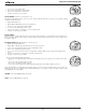
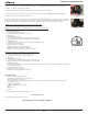
• Slide a new 3 volt type CR2450 Lithium Battery, ( - ) negative side down into the Battery Compartment. Slide it in from the
right side and ensure that it slides under the contact clip on the left rim (Fig. 128).
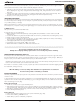
• Orient the Retaining Bar across the lower portion of the Battery and carefully push it down into position (Fig. 129).
Battery Cover and Retaining Ring Installation
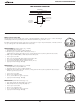
• Lightly lubricate a new Cover O-ring* with silicone grease and place it on the inner rim of the Battery Cover (Fig. 130).
Ensure that it is evenly seated.
*The O-ring must be a genuine AERIS part that can be purchased from an Authorized AERIS Dealer. Use of any other
O-ring will void the warranty.
• Slide the Cover Ring, top portion first (small opening), onto your thumb.
• Carefully place the Battery Cover (with O-ring) into position on the rim of the Battery Compartment, then press it evenly and
completely down into place with your same thumb.
• Maintain the Battery Cover securely in place and, using your other hand, slide the Cover Ring down off your thumb and into
position around the battery compartment.
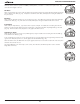
• The tabs on the Cover Ring fit down into the two slots located at the 2 and 8 o'clock positions.
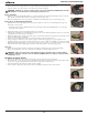
• Using your fingers, turn the Ring counter clockwise 5 degrees until the tabs engage (Fig. 131), then tighten it 5 more
degrees by turning it counter clockwise with the aide of the cover tool (Fig. 132A) or a small blade screwdriver (Fig. 132B).
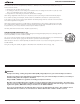
• While tightening the Retaining Ring, exert continuous inward pressure on it until it is secured in the proper position. A small
symbol located on the Ring should be aligned with the Locked symbol located on the Housing (Fig. 133a)
Inspection
• Activate the unit and watch carefully as it performs a full diagnostic and battery check, and enters Watch Mode.
• Observe the LCD display to ensure it is consistently clear and sharp in contrast throughout the screen.
WARNING: If there are any portions of the display missing or appearing dim, or if a Low Battery
condition is indicated, return the unit to an Authorized AERIS Dealer for a complete evaluation before
attempting to use it.
RETURNING THE MODULE TO BOOT
• If the boot was fitted with a spacer and it was previously removed, replace the spacer into the boot.
• Orient the module over the opening in the boot, and dip the bottom edge into it while pressing the top edge with the palm
of your hand. Stop pressing when the bottom edge of the module has just entered the boot.
• Correct the alignment of the module as needed so that it is straight.
• Press the module completely into place with your thumbs, watching the alignment, until it snaps into place.
Fig. 128 - INSERTING
BATTERY
Fig. 129 - RETAINING BAR
Fig. 130 - COVER O-RING
Fig. 131 - ENGAGING TABS
Fig. 132A - SECURE COVER
(using cover tool)
Fig. 133 - RING SECURE
Fig. 132B - SECURE COVER
(using screwdriver)