CoolMax SRX HV Charge Controller Installation and Operation User Manual Models SRX HV 300/30 SRX HV 300/40
USER MANUAL COOLMAX SRX HV – Wall Mount Australian Energy Research Labs AER07.004 – G3 Rev 8 28th September 2020 About Australian Energy Research Laboratories Australian Energy Research Laboratories (AERL) was founded by Stuart Watkinson (BE Elec. Eng., Grad. M.I.E.A) in 1985 to commercialize the “Power Optimizer”, a revolutionary solution to a complex problem, developed while studying at the University of Queensland in Brisbane, Australia.
USER MANUAL COOLMAX SRX HV – Wall Mount Australian Energy Research Labs AER07.004 – G3 Rev 8 28th September 2020 Table of Contents Warranty Conditions ....................................................................................................................................... 6 Specifications .................................................................................................................................................. 7 Introduction .............................................
USER MANUAL COOLMAX SRX HV – Wall Mount Australian Energy Research Labs AER07.004 – G3 Rev 8 28th September 2020 Communications Protocols .................................................................................................................... 29 Master/Slave Configuration ............................................................................................................... 30 Troubleshooting ...............................................................................................
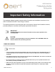
USER MANUAL COOLMAX SRX HV – Wall Mount Australian Energy Research Labs AER07.004 – G3 Rev 8 28th September 2020 Important Safety Information This Installation Manual contains important safety information and installation instructions for the AERL COOLMAX SRX MPPT Solar Charge Controller. The following symbols are used throughout this user manual to indicate ideal installation methods, potentially dangerous conditions and important operational information.
USER MANUAL COOLMAX SRX HV – Wall Mount Australian Energy Research Labs AER07.004 – G3 Rev 8 28th September 2020 Warranty Conditions 1 Warranty Duration from the Date of Purchase Warranty Requirements Total Warranty Duration 1. You are the original purchaser of the CoolMax SRX. 3 Years 2. You are the original purchaser and registered your warranty online within 60 days of installation. 5 Years Our goods come with guarantees that cannot be excluded under the Australian Consumer Law.
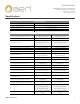
USER MANUAL COOLMAX SRX HV – Wall Mount Australian Energy Research Labs AER07.004 – G3 Rev 8 28th September 2020 Specifications General Specifications Parameter Weight Dimensions (L x W x H) Enclosure Type Input / Output Power Connectors Characteristics Typical 6.
USER MANUAL COOLMAX SRX HV – Wall Mount Australian Energy Research Labs AER07.004 – G3 Rev 8 28th September 2020 Introduction Thanks for purchasing an Australian made CoolMax Series Charge Controller. AERL charge controllers offer an efficient and reliable charging process that not only maintains battery efficiency and life but maximizes power generation by utilizing the full potential of your PV array.
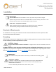
USER MANUAL COOLMAX SRX HV – Wall Mount Australian Energy Research Labs AER07.004 – G3 Rev 8 28th September 2020 Installation IMPORTANT The COOLMAX SRX must be installed in a clean, dry location away from direct sunlight. Optimal cooling is achieved when the COOLMAX SRX is mounted vertically. A minimum of 15cm should be kept clear above the COOLMAX SRX to allow for air flow.
USER MANUAL COOLMAX SRX HV – Wall Mount Australian Energy Research Labs AER07.004 – G3 Rev 8 28th September 2020 Ground Fault Detection & Interruption IMPORTANT Effective 11th July 2015, all solar PV installations in Australia and New Zealand require an external earth fault alarm to be installed on equipment classified as Power Conversion Equipment (PCE). As Solar Charge Controllers (CoolMax SRX) fall under this classification, they will require an earth fault alarm to be installed.
USER MANUAL COOLMAX SRX HV – Wall Mount Australian Energy Research Labs AER07.004 – G3 Rev 8 28th September 2020 Ground Fault Detection & Interruption Solutions Recommended solutions can be found illustrated below. Ground Fault Protection Circuit Remote Ground Fault Indication (Options) Negative Grounded Positive Grounded Floating AERL Optional GFDI Device AERL Optional GFDI Device AERL EarthGuard Part No. AER-GFDI-N Part No. AER-GFDI-P Part No.
USER MANUAL COOLMAX SRX HV – Wall Mount Australian Energy Research Labs AER07.004 – G3 Rev 8 28th September 2020 Mounting the Controller The COOLMAX SRX should be fixed to a vertical surface using the M5 screws provided. The SRX has 8 wall mounting holes in the chassis flanges as demonstrated below in Figure 2A. Figure 2A: SRX Mounting Hole Locations AER07.
USER MANUAL COOLMAX SRX HV – Wall Mount Australian Energy Research Labs AER07.004 – G3 Rev 8 28th September 2020 Mounting Clearances When mounting the SRX, a clearance zone around the device must be adhered to for optimal cooling of the controller under full load. Please refer to the Figure 2B below. Figure 2B: SRX Mounting Clearances AER07.
USER MANUAL COOLMAX SRX HV – Wall Mount Australian Energy Research Labs AER07.004 – G3 Rev 8 28th September 2020 Wiring Information This section will provide information and instructions for safely wiring up the CoolMax SRX. Wire and Disconnect Sizing IMPORTANT • • Wire sizes must comply with local and national standards. Input conductors and circuit breakers must be rated at 1.56 times the short-circuit current of the PV array. Copper wiring must be rated at 75°C or higher.
USER MANUAL COOLMAX SRX HV – Wall Mount Australian Energy Research Labs AER07.004 – G3 Rev 8 28th September 2020 Wiring Compartment CAUTION – Hazard All CoolMax SRX wiring must enter the unit through the correctly labelled cable glands in the base plate or the rear entry ports inside the enclosure. Under absolutely no circumstances should holes be drilled anywhere into the unit to make other cable entry points.
USER MANUAL COOLMAX SRX HV – Wall Mount Australian Energy Research Labs AER07.004 – G3 Rev 8 28th September 2020 Wiring Polarity CAUTION – Equipment Damage Reversing the polarity of either the input or output may damage the CoolMax SRX and void product warranty. Confirm polarity with a DVM prior to closing the I/O breakers. With the access cover removed, the internal I/O terminals will be visible. Refer to Figure 3 below. Figure 3: SRX Access Cover Removed AER07.
USER MANUAL COOLMAX SRX HV – Wall Mount Australian Energy Research Labs AER07.004 – G3 Rev 8 28th September 2020 Operation Powering Up The CoolMax SRX will power up when a PV or Battery voltage is applied. Note: Minimum voltage required for initial start-up is 40 Vdc. When the COOLMAX SRX is first powered the on, the Real Time Screen (Figure 4A) is the first screen to appear.
USER MANUAL COOLMAX SRX HV – Wall Mount Australian Energy Research Labs AER07.004 – G3 Rev 8 28th September 2020 Programming the Device The CoolMax SRX is programmed and controlled via the touch screen display located on the front of the device. The location of the touch screen can be seen in Figure 4B below. The screen allows the user to view real time telemetry, edit the charge profile and view alarms, alerts and system information. Figure 4B: CoolMax Touch Screen Location AER07.
USER MANUAL COOLMAX SRX HV – Wall Mount Australian Energy Research Labs AER07.004 – G3 Rev 8 28th September 2020 Battery Charge Profile IMPORTANT The CoolMax SRX default charge profiles are intended for Lead Acid (PbA) battery solutions. AERL does support some other battery chemistries such as Lithium options that do not require external BMS communications. I.e. GenZ, PPE, Simpliphi, etc.
USER MANUAL COOLMAX SRX HV – Wall Mount Australian Energy Research Labs AER07.004 – G3 Rev 8 28th September 2020 Charge Profile Configuration The CoolMax SRX allows for extensive flexibility when it comes to charge profile parameters to suit numerous different modern battery chemistries and manufacturers requirements. Our charge profile allows for the configuration of the Battery Charge Rate, and the Absorb, Float and Re-Bulk voltage points.
USER MANUAL COOLMAX SRX HV – Wall Mount Australian Energy Research Labs AER07.004 – G3 Rev 8 28th September 2020 Setting the Battery Charge Profile Setting the battery charge profile can be done by following the steps below. Step 1 – Tap the MENU button located in the left-hand corner of the live telemetry screen. Step 2 – Tap the SETTINGS button located at the top of the MAIN MENU. Step 3 – Tap the SET POINTS button located at the top of the SETTINGS MENU. AER07.
USER MANUAL COOLMAX SRX HV – Wall Mount Australian Energy Research Labs AER07.004 – G3 Rev 8 28th September 2020 Step 4 – You are now on the SET POINTS screen. The setting currently selected will be highlighted in orange. Tap EDIT to edit the selected option or UP/DOWN to move between settings. Battery Capacity: 10 kWh Charge Rate: 1C IMPORTANT There are two pages (1/2, 2/2) of charge profile settings.
USER MANUAL COOLMAX SRX HV – Wall Mount Australian Energy Research Labs AER07.004 – G3 Rev 8 28th September 2020 Step 6 – Adjust the setting using the UP and DOWN buttons until the desired voltage is specified and then tap Apply. Step 7 – Finally, save your charge profile by tapping Apply. The CoolMax will save your settings and proceed to reset/reboot.
USER MANUAL COOLMAX SRX HV – Wall Mount Australian Energy Research Labs AER07.004 – G3 Rev 8 28th September 2020 Enabling the Output To activate output battery charge, press the ON/OFF button located at the bottom of the CoolMax Real Time Telemetry screen (Figure 4A). This will take you to the OUTPUT CONTROL screen which will allow you to enable the output (Figure 6).
USER MANUAL COOLMAX SRX HV – Wall Mount Australian Energy Research Labs AER07.004 – G3 Rev 8 28th September 2020 Setting the Time/Date From the Real Time Telemetry Screen (Figure 5), select the Menu button at the bottom left of the page to take you to the MAIN MENU screen page (Figure 7). Figure 7: Main Menu Screen Figure 8: Settings Screen Figure 9: Time / Date Screen Then press the SETTINGS button on the MAIN MENU screen page and this will take you to the SETTINGS Screen (Figure 8).
USER MANUAL COOLMAX SRX HV – Wall Mount Australian Energy Research Labs AER07.004 – G3 Rev 8 28th September 2020 Auxiliary Functions The CoolMax SRX offers several auxiliary functions via the 8-Pin connection on the bottom of the device. The pin-out for this connector is demonstrated in Figure 11 below. The corresponding female version of the 8-Pin connector is available from AERL (Part Number: AUX-8-PIN-F). Figure 11: AUX (8-PIN) Connector Pin-Out AER07.
USER MANUAL COOLMAX SRX HV – Wall Mount Australian Energy Research Labs AER07.004 – G3 Rev 8 28th September 2020 Battery Temperature Compensation IMPORTANT To utilize the CoolMax SRX battery temperature compensation functionality, an AERL CoolMax SRX Remote Temperature Sensor will be required. Part Number: SRX-RTS Temperature compensation measures the temperature of the batteries and adjusts the float and absorb voltage set points to the ideal voltage for batteries at that temperature.
USER MANUAL COOLMAX SRX HV – Wall Mount Australian Energy Research Labs AER07.004 – G3 Rev 8 28th September 2020 Relay Alarms / GENSET Control The CoolMax SRX features two built-in 12V/1A relays for alarm and indication purposes. Relay 1 (RLY 1) is utilized is a float indication relay and will activate when the battery bank reaches float. This relay can be used to alert the associated battery inverter to the battery’s state of charge.
USER MANUAL COOLMAX SRX HV – Wall Mount Australian Energy Research Labs AER07.004 – G3 Rev 8 28th September 2020 Communications Protocols The CoolMax SRX features both Controller Area Network (CAN bus) and ModBus RTU (RS485) capabilities for remote monitoring and control functionality. The relevant protocol registry maps for integration are available from AERL on request. Both networking protocols can be accessed via the RJ45 connector located on the bottom of the CoolMax SRX.
USER MANUAL COOLMAX SRX HV – Wall Mount Australian Energy Research Labs AER07.004 – G3 Rev 8 28th September 2020 Master/Slave Configuration To utilize the Master/Slave functionality of the CoolMax SRX, an RJ45 ethernet cable, a USB Mini B cable and the CoolMax Utility Software are required to link the units over the CAN bus network and configure the relevant comms settings. IMPORTANT The CoolMax Utility Software is available from the Downloads section of the AERL website. Visit www.aerl.com.
USER MANUAL COOLMAX SRX HV – Wall Mount Australian Energy Research Labs AER07.004 – G3 Rev 8 28th September 2020 2. Link the two controllers via an RJ45 Ethernet (CAT 5/6) cable as demonstrated in Figure 14 below. Figure 14: Connecting the SRX Comms for Master/Slave over CAN bus. AER07.
USER MANUAL COOLMAX SRX HV – Wall Mount Australian Energy Research Labs AER07.004 – G3 Rev 8 28th September 2020 3. You can now power on controllers and configure the Master’s Charge Profile via the LCD. a. Refer to Pages 19, 20 and 21 for instructions on configuring the charge profile for your relevant application. 4. After configuring the Master’s Charge Profile, input the same settings into the Slave’s Charge Profile. a.
USER MANUAL COOLMAX SRX HV – Wall Mount Australian Energy Research Labs AER07.004 – G3 Rev 8 28th September 2020 7. Navigate to the “User Settings” tab on the top right-hand side of the program and change the “Is Slave” from FALSE to TRUE using the drop-down menu as demonstrated below in Figure 16. Figure 16: Putting the SRX controller into Slave Mode. 8. Change the CAN Bus ID to 1424 and hit “Save” and then subsequently “Reset” which is located next to the “Connect/Disconnect” button. 9.
USER MANUAL COOLMAX SRX HV – Wall Mount Australian Energy Research Labs AER07.004 – G3 Rev 8 28th September 2020 Troubleshooting If the COOLMAX SRX detects a warning or error, an alarm will be triggered in the ALARMS tab on the Real Time Telemetry screen. Error Codes Please refer to the table below for Warning Codes starting with “W” and the table located on Pg. 29/30 for Fault Codes starting with “F”.
USER MANUAL COOLMAX SRX HV – Wall Mount Australian Energy Research Labs AER07.004 – G3 Rev 8 28th September 2020 Please refer to the table below for Fault Codes. Fault Code Error Error Description F001 Low Output Voltage Detected Low output voltage has been detected. Confirm the battery is connected to the controller. F002 High Output Voltage Detected High output voltage has been detected. F003 High Output Current Detected High output current has been detected.
USER MANUAL COOLMAX SRX HV – Wall Mount Australian Energy Research Labs AER07.004 – G3 Rev 8 28th September 2020 Fault Code Error Error Description F012 High PV Voltage Critical High PV Voltage has been detected. The device has shutdown to prevent system damage. F013 High Output Current Critical High output current has been detected. The device has shutdown to prevent system damage. The detected battery voltage is outside of the allowable operating range for the selected nominal battery voltage.
USER MANUAL COOLMAX SRX HV – Wall Mount Australian Energy Research Labs AER07.004 – G3 Rev 8 28th September 2020 Note: The CoolMax troubleshooting guide and documentation is being improved regularly. In the event that the relevant situation is not documented, please contact AERL at either support@aerl.com.au or on 07 3129 0330, we’re happy to help assist with any queries you may have. AER07.
USER MANUAL COOLMAX SRX HV – Wall Mount Australian Energy Research Labs AER07.004 – G3 Rev 8 28th September 2020 This page has intentionally been left blank. AER07.
USER MANUAL COOLMAX SRX HV – Wall Mount Australian Energy Research Labs AER07.004 – G3 Rev 8 28th September 2020 This page has intentionally been left blank. AER07.