
Operation Manual


12
BMS - pCO5 1309 5806600
EN
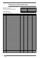
Modbus
address
(BMS 1)
AerWeb300
address
(BMS2)
CAREL
Add.
Description
Unit of
meas-
urement
Min Max R/W
253 5046 45 Upper part peak counter, circuit 1 CP1A --- 0 999
R
254 5047 46 Lower part peak counter, circuit 1 CP1A --- 0 999 R
255 5048 47 Upper part peak counter, circuit 1 CP1B --- 0 999 R
256 5049 48 Lower part peak counter, circuit 1 CP1B --- 0 999 R
257 5050 49 Upper part peak counter, circuit 2 CP1 --- 0 999 R
258 5051 50 Lower part peak counter, circuit 2 CP1 --- 0 999 R
259 5052 51 Upper part peak counter, circuit 2 CP1A --- 0 999 R
260 5053 52 Lower part peak counter, circuit 2 CP1A --- 0 999 R
261 5054 53 Upper part peak counter, circuit 2 CP1B --- 0 999 R
262 5055 54 Lower part peak counter, circuit 2 CP1B --- 0 999 R
263 5056 55
264 5057 56
265 5058 57
266 5059 58
267 5060 59
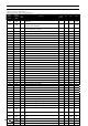
268 5061 60 Code NRL - Size --- 0 20 R/W
269 5062 61 Code NRL - Comp. Type --- 0 3 R/W
270 5063 62 Code NRL - Valve --- 0 2 R/W
271 5064 63 Code NRL - model --- 0 3 R/W
272 5065 64 Code NRL - recovery --- 0 3 R/W
273 5066 65 Code NRL - Version --- 0 3 R/W
274 5067 66 Code NRL – Batteries --- 0 2 R/W
275 5068 67 Code NRL – Fan --- 0 3 R/W
276 5069 68 Code NRL - Supply --- 0 2 R/W
277 5070 69 Code NRL - Storage
278 5071 70 Unit range identification code (0=NRL) 0 999 R
408 5201 200 Circ 1 power % 0 999 R
409 5202 201 Circ 2 power % 0 999 R
410 5203 202
Circuit 1 defrost state (0=DISABLED, 1=BYPASS,
3=CALCULATION OF DECAY, 11=CYCLE INVERSION STAND-BY,
13=DEFROST START, 14=DEFROST IN PROGRESS, 15=CYCLE
INVERSION STAND-BY, 17=DEFROST END, 20=FIRST DEFROST)
--- 0 99 R
411 5204 203
Circuit 1 defrost events (1=External high temperature,
2=Circuit off, 3=BP above minimum threshold, 4=Minimum
time between defrosts, 5=CP start, 6=new BP reference,
7=start to BP limit, 8=delta P start, 9=liquid temperature
OK, 10=Minimum defrost time, 11=another circuit stand-by,
12=bypass first start, 13=Low liquid temperature, 14=high
TGP start, 15=forced)
--- 0 99 R
412 5205 204
Circuit 2 defrost state (0=DISABLED, 1=BYPASS,
3=CALCULATION OF DECAY, 11=CYCLE INVERSION STAND-BY,
13=DEFROST START, 14=DEFROST IN PROGRESS, 15=CYCLE
INVERSION STAND-BY, 17=DEFROST END, 20=FIRST DEFROST)
--- 0 99 R
413 5206 205
Circuit 2 defrost events (1=External high temperature,
2=Circuit off, 3=BP above minimum threshold, 4=Minimum
time between defrosts, 5=CP start, 6=new BP reference,
7=start to BP limit, 8=delta P start, 9=liquid temperature
OK, 10=Minimum defrost time, 11=another circuit stand-by,
12=bypass first start, 13=Low liquid temperature, 14=high
TGP start, 15=forced)
--- 0 99 R