M A N UA L E D ’ U S O E I N S TA L L A Z I O N E I N S TA L L AT I O N A N D U S E R M A N UA L MANUEL D’UTILISATION ET D’INSTALLATION BEDIENUNGS- UND INSTALLATIONSANLEITUNG M A N UA L D E U S O E I N S TA L AC I Ó N ventilconvettore per installazione a parete wall-mounted fan coil UNIT ventilo-convecteur pour installation murale Gebläsekonvektor für Wandinstallation entiloconvector para instalación de pared FCW FCW 212V FCW 312V FCW 412V FCW 212VN FCW 312VN FCW 412VN FCW 213V FCW 313V FCW 41
INDICE • CONTENTS • INDEX • INHALT • ÍNDICE Trasporto • Transport • Transport • Transport • Transporte Dichiarazione di conformità • Declaration of Conformity • Déclaration de conformité • Konformitätserklärung • Declaración de conformidad 3 4 Italiano 5 English 29 Français 53 Deutsch 77 Español 101 trasporto • TRANSPORT • traNSPORT • TRANSPORT • Transporte NON bagnare. Tenere al riparo dalla pioggia NON calpestare Do not wet.
FCW VENTILCONVETTORE FAN COIL UNIT Ventilo-convecteurs Gebläsekonvektor FAN COIL AERMEC S.p.A. I-37040 Bevilacqua (VR) Italia – Via Roma, 996 Tel. (+39) 0442 633111 Telefax (+39) 0442 93730 – (+39) 0442 93566 www.aermec.com - info@aermec.
indice Osservazioni • Avvertenze di sicurezza • Ricevimento dell'unità • Imballo • Smaltimento 6 Manutenzione • Problemi e soluzioni 7 Descrizione dell’unità 8 Componenti principali • Descrizione dei componenti 9 Informazioni generali 10 Informazioni importanti • Limiti di funzionamento 11 Orientamento del flusso d’aria 12 Segnalazioni e tasti di controllo FCW con Controllo con scheda elettronica a microprocessore 13 TLW2 - Telecomando a raggi infrarossi 14 PFW2 - Pannello comandi remoto a
Italiano OSSERVAZIONI Conservare i manuali in luogo asciutto, per evitare il deterioramento, per almeno 10 anni per eventuali riferimenti futuri. Leggere attentamente e completamente tutte le informazioni contenute in questo manuale. Prestare particolarmente attenzione alle norme d’uso accompagnate dalle scritte “PERICOLO” o “ATTENZIONE” oppure dai “Simboli di sicurezza“ in quanto, s e n o n o s s e rva t e , p o s s o n o causare danno alla macchina e/o a persone e cose.
Italiano MANUTENZIONE MANUTENZIONE ORDINARIA La manutenzione ordinaria, può essere eseguita anche dall’utente, consiste in una serie di operazioni semplici, grazie alle quali il ventilconvettore può operare alla massima efficienza. Interventi: - Pulizia esterna, frequenza settimanale, da eseguire con un panno umido (bagnato in acqua al massimo a 40 °C) e sapone neutro; evitare altri detergenti e solventi di qualsiasi tipo.
Italiano FCW - VENTILCONVETTORE Il ventilconvettore FCW Aermec è realizzato con materiali di qualità superiore, nel rigoroso rispetto delle normative di sicurezza, "FCW" è di facile utilizzo e vi accompagnerà a lungo nell'uso. Il ventilconvettore è un terminale per il trattamento dell’aria di un ambiente interno sia nella stagione invernale sia in quella estiva.
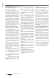
Italiano COMPONENTI PRINCIPALI 1 2 3 4 5 6 7 8 9 10 Pannello frontale Deflettore orizzontale mandata aria Deflettore verticale mandata aria Filtro aria Batteria di scambio termico Interruttore ausiliario di emergenza Morsettiera collegamenti elettrici Elemento frontale Telaio Display 10 FCW 9 1 2 3 5 4 3 6 7 8 TLW2 PFW2 descrizione dei componenti PANNELLO FRONTALE L’aria viene aspirata dalle feritoie. Sollevando il pannello si ha accesso ai filtri aria ed alle altre parti interne.
Italiano informazioni generali • Versioni senza Controllo con scheda elettronica a microprocessore: Con e senza valvole dell'acqua. Le versioni senza Controllo con scheda elettronica a microprocessore richiedono di essere abbinate ad un dispositivo di comando (accessorio) da scegliere tra pannelli comandi comandi standard (con funzioni compatibili alla configurazione del ventilconvettore) oppure di essere abbinate ad un termostato del sistema VMF.
N on in f ilare oggetti sull’uscita dell’aria Non inserire oggetti di nessun tipo nelle feritoie di uscita dell’aria. Ciò potrebbe provocare ferimenti alla persona e danni al ventilatore. ATTENZIONE: il ventilconvettore è collegato alla rete elettrica ed al circuito idraulico, un intervento da parte di personale non provvisto di specifica competenza tecnica può causare danni allo stesso operatore, all’apparecchio ed all’ambiente circostante.
Italiano IMPORTANTE Nota per i ventilconvettori serie FCW dotati di Controllo con scheda elettronica a microprocessore a bordo. - I due modelli di comando, pannello a filo (PFW2) e telecomando (TLW2), non possono essere usati contemporaneamente sullo stesso ventilconvettore. – Se il ventilconvettore viene spento tutte le impostazioni precedentemente effettuate vengono mantenute in memoria eccetto che le funzioni SLEEP e TIMER.
Quando il ventilconvettore riceve tensione emette un segnale acustico. Quando il ventilconvettore è alimentato, ma non è acceso, tutti i led sono spenti. 1 - DISPLAY TEMPERATURA / CODICE ERRORE - Nel funzionamento normale indica la temperatura. - Se il set della temperatura cambia il valore in °C lampeggia per 5 secondi. - Errore sonda ambiente, E1 lampeggia. - Errore sonda interna, E2 lampeggia. - Errore sonda acqua, E3 lampeggia. - Errore sonda temperatura acqua, E4 lampeggia.
Italiano TLW2 - telecomando a raggi infrarossi IMPORTANTE Nota per i ventilconvettori serie FCW dotati di Controllo con scheda elettronica a microprocessore a bordo. - I due modelli di comando, pannello a filo (PFW2) e telecomando (TLW2), non possono essere usati contemporaneamente sullo stesso ventilconvettore. – Se il ventilconvettore viene spento tutte le impostazioni precedentemente effettuate vengono mantenute in memoria eccetto che le funzioni SLEEP e TIMER.
Con telecomando acceso (ON) il display visualizza le impostazioni date all’unità, con telecomando spento (OFF) il display è spento o visualizza solo il timer per l’accensione programmata (se attivato).
Italiano PFW2 - Pannello comandi remoto a filo Importante Nota per i ventilconvettori serie FCW dotati di Controllo con scheda elettronica a microprocessore a bordo. - I due modelli di comando, pannello a filo (PFW2) e telecomando (TLW2), non possono essere usati contemporaneamente sullo stesso ventilconvettore. – Se il ventilconvettore viene spento tutte le impostazioni precedentemente effettuate vengono mantenute in memoria eccetto che le funzioni SLEEP e TIMER.
Italiano Programma automatico (“AUTO”) Il programma richiede che nell’impianto circoli acqua refrigerata o acqua calda. 1) Premere il tasto acceso-spento o Il ventilconvettore entra in funzione. Il ventilconvettore automaticamente si attiva in modo Raffrescamento, Riscaldamento o in banda morta (attesa) in funzione della temperatura dell'acqua.
Italiano Programma raffreddamento (cool) Il programma richiede che nell’impianto circoli acqua refrigerata. 1) Premere il tasto acceso-spento o Il ventilconvettore entra in funzione. Il ventilconvettore automaticamente si attiva in modo Raffrescamento. o 2) remere il tasto mode Premere il tasto MODE ripetutamente finchè compare sul display la scritta COOL (TLW2) o il led indica COOL (PFW2).
Italiano Programma deumidificazione (dry) Il programma richiede che nell’impianto circoli acqua refrigerata. 1) Premere il tasto acceso-spento o Il ventilconvettore entra in funzione e si accende il display sull’unità. 2) remere il tasto mode o Premere il tasto MODE ripetutamente finchè compare sul display la scritta DRY (TLW2) o il led indica DRY (PFW2).
Italiano accensione programmata tramite TIMER 1) accendere con i tasti o – impostare sul telecomando le condizioni (MODE, FAN, TEMP) che desideriamo siano attive al riavvio – spegnere con i tasti o 2) ATTIVARE TIMER ON CON I TASTI o 3) regolare il TIMER di accensione con i tasti o – il tasto con il simbolo permette incrementi di 1 ora – il tasto con il simbolo permette decrementi di 1 ora Il display indica solamente le ore di fermo prima dell’accensione programmata, TLW2 da 1 a 18 ore, PLW2 da 1 a 24 ore,
Italiano dati dimensionali [mm] C 150mm A 150mm B 150mm 1500 FCW212V - FCW212VN FCW213V - FCW213VN FCW21VL - FCW21VLN FCW312V - FCW312VN FCW313V - FCW313VN FCW31VL - FCW31VLN FCW412V - FCW412VN FCW413V - FCW413VN FCW41VL - FCW41VLN A B C 880 298 180 990 305 180 1172 360 210 1900 - 2200 mm mm J I J J I J FCW 212V - 213V - 21VL - 212VN - 213VN - 21VLN 312V - 313V - 31VL - 312VN - 313VN - 31VLN 412V - 413V - 41VL - 412VN - 413VN - 41VLN A 880 990 1172 B 298 305 360 C 190 191 139
Italiano dilatazioni termiche degli elementi (plastici e metallici), ciò comunque non provoca danni all’unità se non si supera la massima temperatura di esercizio. Vengono qui riportate le indicazioni essenziali per una corretta installazione delle apparecchiature. Si lascia comunque all'esperienza dell'installatore il perfezionamento di tutte le operazioni a seconda delle esigenze specifiche.
Italiano state ultimate (collegamenti elettrici e idraulici, fissaggio del ventilconvettore e collegamento dello scarico condensa) chiudere il foro nel muro con materiale di riempimento. - Sfiatare mediante l’apposita valvola lo scambiatore. - Completare il rimontaggio dei componenti dell’unità facendo attenzione che residui dei materiali usati per l’installazione non blocchino la ventola o ostruiscano i filtri o le gliglie. - Dopo l’installazione eseguire una prova di funzionamento del ventilconvettore.
Italiano Collegamenti elettrici Pannello frontale Morsettiera alimentazione elettrica Basamento onnipolare magnetotermico max. 2A Attenzione: prima di effettuare 250V (CIRCUIT BREAKER) con distanza qualsiasi intervento, assicurarsi che minima di apertura dei contatti di 3mm. l’alimentazione elettrica sia disinserita.
Italiano - installazione Pannello a filo PFW2 (accessorio) Accessorio indispensabile al funzionamento del ventilconvettore, in alternativa al telecomando TLW2, i due modelli di comando disponibili non possono coesistere. Un pannello PFW2 può controllare un solo ventilconvettore. Il pannello può essere fissato direttamente alla parete con due viti oppure ad una scatola elettrica rettangolare unificata a 3 moduli.
English Dear customer, Thank you for choosing an AERMEC product. It is the fruit of many years of experience and special design studies and has been made of the highest grade materials and with cutting edge technology. The CE marking indicates that the products comply with the essential requirements of the applicable European Community directives. The quality level is being constantly monitored, so AERMEC products are synonymous with Safety, Quality and Reliability.
For any irregularities not foreseen by this manual, promptly contact your local After Sales Service. The device must be installed in such a way that maintenance and/or repair operations are possible. The warranty of the device does not in any case cover costs owing to ladder trucks, lifts or other lifting systems that may be required in order to carry out repairs under warranty. AERMEC S.p.A.
English MAINTENANCE ORDINARY MAINTENANCE The ordinary maintenance can be carried out by the user and consists of a series of simple operations, which will ensure that the fan coil unit operates at full efficiency. Operations: - External cleaning, to be done with a damp cloth (soaked in water no hotter than 40 °C) and a neutral detergent avoid using any other type of detergent or solvent. Do not splash water on interior or exterior surfaces of the fan coil unit (it could cause short circuits).
English FCW wall-mounted FAN COIL UNIT The Aermec FCW fan coil unit is made with materials of superior quality in strict compliance with safety regulations. The "FCW" is easy to use and will have a long life. The fan coil unit is a terminal unit for conditioning internal air both in winter and summer. The FCW fan coil unit for wall mounted installation concentrates high technological and functional characteristics that make it the ideal climate control unit for all environments.
English MAIN COMPONENTS 1 2 3 4 5 6 7 8 9 10 Front panel Horizontal air discharge blades Vertical air discharge blades Air filter Heat exchanger coil Auxiliary emergency switch Electric terminal connections Front case Frame Display 10 FCW 9 1 2 3 5 4 3 6 7 TLW2 8 PFW2 description of components FRONT PANEL The air intake is via the slots.
• Versions without microprocessor controller: With or without water valve. Versions without microprocessor controller need to be combined with a control panel (accessory) chosen from standard control panels (compatible with the configuration of the fan coil unit) or be combined with a thermostat from the VMF system.
English Important information WARNING: The fan coil unit is connected to the power supply and a water circuit. Operations performed by persons without the required technical skills can lead to personal injury to the operator or damage to the unit and surrounding objects. MALFUNCTION In the case of a malfunction remove power to the unit then reapply it and start the unit again. If the problem occurs again, call your area After-Sales service department promptly.
DIRECTION OF THE AIR FLOW The blades on the air discharge are arranged to direct the air in two directions: – vertical blades, to be adjusted manually – motorised horizontal blades for versions with microprocessor controller, to be adjusted only by means of the TLW2 remote control or the PFW2 wired control panel – horizontal blades for versions without microprocessor controller to be adjusted manually.
English FCW WITH MICROPROCESSOR CONTROLLER - FRONT PANEL DISPLAY When the fan coil unit is powered up it emits a beep. When the fan coil unit is powered but not on, all the LEDs are off.
IMPORTANT Note for FCW series with microprocessor controller: - The two control types, wired control panel (PFW2) and remote control (TLW2), cannot be used at the same time on the same fan coil unit. – If the fan coil is off, all the previous settings made are kept in the memory except for the TIMER setting and SLEEP mode. – If the fan coil is turned on using the (ON/OFF) key, the TIMER setting and SLEEP mode are cancelled. 17 16 1 4 3 2 12 5 15 14 9 8 7 13 6 10 11 1 - ON/OFF Turning on and off.
English Liquid crystal display With the remote control on (ON), the display shows the settings of the unit, with the remote control off (OFF) the display is off and only displays the timer for the programmed activation (if active).
IMPORTANT Note for FCW series with microprocessor controller: - The two control types, wired control panel (PFW2) and remote control (TLW2), cannot be used at the same time on the same fan coil unit. – If the fan coil is off, all the previous settings made are kept in the memory except for the TIMER setting and SLEEP mode. – If the fan coil is turned on using the (ON/OFF) key, the TIMER setting and SLEEP mode are cancelled. 1 - ON/OFF Turning the unit on and off.
English Automatic programme (AUTO) The programme requires the system to circulate chilled or hot water. 1) Press the on/off or KEYS The fan coil unit comes on. The fan coil unit will automatically switch on in Cool mode, Heat mode or in the dead band (waiting) depending on the water temperature. 2) Press the mode KEY Press the MODE key repeatedly until the word AUTO appears on the display (TLW2) or the LEDs on wired control panel (PFW2) turns on HEAT and COOL.
English Cooling programme (cool) The programme requires the system to circulate chilled water. 1) Press the on/off or KEYS The fan coil unit comes on. The fan coil unit automatically starts in cooling mode. 2) Press the mode KEY Press the MODE key repeatedly until the word COOL appears on the display (TLW2) or the LEDs on wired control panel (PFW2) turns on COOL.
English DehumIdification programme (dry) The programme requires the system to circulate chilled water. 1) Press the on/off or turn on with The fan coil comes on and the display is switched on. or keys OR 2) Press the key mode Press the MODE key repeatedly until the word DRY appears on the display (TLW2) or the LEDs on wired control panel (PFW2) turns on DRY.
English turn on programmed by the TIMER 1) turn on with or keys – Set the required conditions (MODE, FAN, TEMP) on the remote control that you want active when starting the unit.
C 150mm A 150mm 150mm B 1500 mm FCW212V - FCW212VN FCW213V - FCW213VN FCW21VL - FCW21VLN FCW312V - FCW312VN FCW313V - FCW313VN FCW31VL - FCW31VLN FCW412V - FCW412VN FCW413V - FCW413VN FCW41VL - FCW41VLN A B C 880 298 180 990 305 180 1172 360 210 1900 - 2200 mm J J I J J I English dimensions [mm] FCW 212V - 213V - 21VL - 212VN - 213VN - 21VLN 312V - 313V - 31VL - 312VN - 313VN - 31VLN 412V - 413V - 41VL - 412VN - 413VN - 41VLN A 880 990 1172 B 298 305 360 C 190 191 139 D 90 91
Hydraulic connections: Female diam. 1/2”G with flat faced flare connections. The direction of the water flow is indicated on the pipes of the unit. Condensate drain connections: FCW 21 - 31 and 41: Female with internal diameter of Øi 16 mm. The supply and return pipes must be equally sized, made of copper with a minimum diameter of 1/2", suitably insulated to avoid heat dispersion and dripping during cooling operation.
English completed (electrical and hydraulic connections, fan coil unit fixing and condensate drain connection) close the hole in the wall with a suitable filler. - Vent the coil using the air valve provided. - Complete the refitting of the components of the unit paying attention that the debris from the materials used for the installation do not block the fan or obstruct the filters or the grilles. - After installation perform a functional test of the fan coil unit.
English ELECTRICAL WIRING Front panel Power supply terminal block Base Warning: check that the power supply is disconnected before performing operations on the unit. The unit must be connected directly to an electrical outlet or to an independent circuit. Provide a 230V (±10%) power supply. To protect the unit against short circuits, fit a circuit breaker of max. 2A 250V to the power line with a minimum contact opening distance of 3 mm.
English installation of PFW2 wired control panel (accessory) Accessory indispensable for the functioning of the fan coil unit. Alternative to the remote control TLW2. The two control systems cannot be used together. A PFW2 wired control panel can only control one fan coil unit. The panel can be fixed directly to the wall with two screws or a rectangular electrical box.
index Observations • Mises en garde de sécurité • Réception des unités • Emballage • Elimination 55 Maintenance • Problèmes et solutions 56 Description de l'unité 57 Principaux composants • Description des composants 58 Informations générales 59 Informations importantes • Limites de fonctionnement 60 Orientation du flux d'air 61 Signalisations et touches de contrôle FCW avec Contrôle avec carte électronique à microprocesseur 62 TLW2 - Télécommande à rayons infrarouges 63 PFW2 - Panneau de
Français REMARQUES Conserver les manuels dans un endroit sec afin d'éviter qu'ils ne se détériorent, pendant 10 ans au moins, en vue d'éventuelles consultations futures. Lire attentivement l'ensemble des informations contenues dans ce manuel. Faire particulièrement attention aux normes d’utilisation accompagnées des inscriptions “DANGER” ou “ATTENTION ” ou des " Symboles de sécurité" car, si elles ne sont pas respectées, elles peuvent provoquer des dommages à la machine et/ou aux personnes et aux biens.
Français MAINTENANCE MAINTENANCE ORDINAIRE La maintenance ordinaire peut être effectuée aussi par l'utilisateur ; elle consiste en une série d'opérations simples grâce auxquelles le ventilo-convecteur peut fonctionner au maximum de son efficacité. Interventions : - Nettoyage extérieur, fréquence hebdomadaire, à effectuer avec un chiffon humide ( humidifié dans une eau à 40°C maximum) et savon neutre ; éviter d'autres détergents et les solvants en tous genres.
Français FCW - VENTILO-CONVECTEUR Fabriqué avec des matériaux de qualité supérieure, dans le respect rigoureux des normes de sécurité, le ventilo-convecteur FCW Aermec est facile à utiliser et il vous accompagnera longtemps. Le ventilo-convecteur est un terminal pour le traitement de l'air dans un espace intérieur aussi bien en été qu'en hiver. Le ventilo-convecteur FCWconcentre des caractéristiques technologiques et fonctionnelles élevées qui en font le moyen de climatisation idéal pour tout espace.
Français COMPOSANTS PRINCIPAUX 1 2 3 4 5 6 7 8 9 10 Panneau frontal Déflecteur horizontal refoulement de l'air Déflecteur vertical refoulement de l'air Filtre à air Batterie d'échange thermique Interrupteur de secours auxiliaire Boîte à bornes des branchements électriques Elément frontal Cadre Affichage 10 FCW 9 1 2 3 5 4 3 6 7 8 TLW2 PFW2 description des composants PANNEAU FRONTAL L'air est aspiré par les fentes d'aération.
Français Informations générales • Versions sans Contrôle avec carte électronique à microprocesseur : Avec et sans les vannes de l'eau. Les versions sans Contrôle avec carte électronique à microprocesseur demandent d'être assorties à un dispositif de commande (accessoire) à choisir entre panneaux de contrôle standard (avec fonctions compatibles avec la configuration du ventiloconvecteur) ou d'être assorties à un thermostat du système VMF.
ATTENTION : le ventilo-convecteur est branché au réseau électrique et au circuit hydraulique ; une intervention effectuée par un personnel dépourvu des compétences techniques spécifiques peut provoquer des dommages à l'opérateur, à l'appareil et au milieu environnant. ANOMALIES DE FONCTIONNEMENT En cas de fonctionnement anormal, couper le courant à l'unité, ensuite le rebrancher et procéder au redémarrage de l'appareil. Si le problème se représente, s'adresser rapidement au Service d'Assistance local.
Français IMPORTANT : Remarque pour les ventilo-convecteurs série FCW équipés de Contrôle avec carte électronique à microprocesseur. - Les deux modèles de commande, panneau câblé (PFW2) et télécommande (TLW2), ne peuvent être utilisés simultanément sur le même ventilo-convecteur. – Si le ventilo-convecteur est éteint, tous les paramètres effectués précédemment sont conservés en mémoire sauf les fonctions SLEEP et TIMER.
Lorsque le ventilo-convecteur est alimenté, il émet un signal acoustique. Lorsque le ventilo-convecteur est alimenté mais qu'il n'est pas allumé, toutes les leds sont éteintes. 1 - ECRAN TEMPERATURE/CODE ERREUR - Durant le fonctionnement normal, il indique la température. - Si le réglage de la température change, la valeur en °C clignote pendant 5 secondes. - Erreur sonde d'ambiance, E1 clignote. - Erreur sonde intérieure, E2 clignote. - Erreur sonde eau, E3 clignote.
Français TLW2 - Télécommande à rayons infrarouges IMPORTANT : Remarque pour les ventilo-convecteurs série FCW équipés de Contrôle avec carte électronique à microprocesseur. - Les deux modèles de commande, panneau câblé (PFW2) et télécommande (TLW2), ne peuvent être utilisés simultanément sur le même ventilo-convecteur. – Si le ventilo-convecteur est éteint, tous les paramètres effectués précédemment sont conservés en mémoire sauf les fonctions SLEEP et TIMER.
Avec la télécommande allumée (ON), l'écran visualise les configurations données à l'unité. Avec la télécommande éteinte (OFF), l'écran est éteint ou il visualise seulement le timer pour l'allumage programmé (si activé).
Français PFW2 - Panneau de contrôle à distance câblé Important : Remarque pour les ventilo-convecteurs série FCW équipés de Contrôle avec carte électronique à microprocesseur. - Les deux modèles de commande, panneau câblé (PFW2) et télécommande (TLW2), ne peuvent être utilisés simultanément sur le même ventilo-convecteur. – Si le ventilo-convecteur est éteint, tous les paramètres effectués précédemment sont conservés en mémoire sauf les fonctions SLEEP et TIMER.
Français Programme automatique ("AUTO") Le programme demande que de l'eau réfrigérée ou de l'eau chaude circule dans l'installation. 1) Appuyer sur la touche allumé-éteint o Le ventilo-convecteur entre en fonction. Le ventilo-convecteur s'active automatiquement en mode rafraichissement, chauffage ou en bande morte (attente) en fonction de la température de l'eau.
Français Programme refroidissement (cool) Le programme demande que de l'eau réfrigérée circule dans l'installation. 1) Appuyer sur la touche allumé-éteint o Le ventilo-convecteur entre en fonction. Le ventilo-convecteur s'active automatiquement en mode Rafraîchissement o 2) Appuyer sur la touche mode Appuyer plusieurs fois sur la touche MODE jusqu'à tant que le mot COOL (TLW2) n'apparaisse sur l'écran ou que la led n'indique COOL (PFW2).
Français Programme déshumidification (dry) Le programme demande que de l'eau réfrigérée circule dans l'installation. 1) Appuyer sur la touche allumé-éteint o Le ventilo-convecteur se met en marche et l'écran de l'unité s'allume. 2) Appuyer sur la touche mode o Appuyer plusieurs fois sur la touche MODE jusqu'à tant que le mot DRY (TLW2) n'apparaisse sur l'écran ou que la led n'indique DRY (PFW2). 3) Appuyer sur les touches o pour régler la température permet d'effectuer des augmentations de 1°C.
Français allumage programmé au moyen du TIMER 1) allumer avec les touches o – sur la télécommande, configurer les conditions (MODE, FAN, TEMP) que vous souhaitez voir activées au rallumage.
Français données dimensionnelles [mm] C 150mm A 150mm B 150mm 1500 FCW212V - FCW212VN FCW213V - FCW213VN FCW21VL - FCW21VLN FCW312V - FCW312VN FCW313V - FCW313VN FCW31VL - FCW31VLN FCW412V - FCW412VN FCW413V - FCW413VN FCW41VL - FCW41VLN A B C 880 298 180 990 305 180 1172 360 210 1900 - 2200 mm mm J I J J I J FCW 212V - 213V - 21VL - 212VN - 213VN - 21VLN 312V - 313V - 31VL - 312VN - 313VN - 31VLN 412V - 413V - 41VL - 412VN - 413VN - 41VLN A 880 990 1172 B 298 305 360 C 190 1
Français L'utilisation d'une eau à des températures élevées pourrait provoquer des craquements dus aux diversesdilatations thermiques des éléments (plastiques et métalliques) sans pour autant endommager l'unité si la température maximale d'exercice n'est pas dépassée. Sont reportées ci-dessous les indications essentielles pour une installation correcte des appareils. Le parachèvement de toutes les opérations est cependant laissé à l’expérience de l’installateur en fonction de vos besoins spécifiques.
Français à la verticale qu'à l'horizontale. - Lorsque toutes les opérations ont été achevées (raccordements électriques et hydraulques, fixation du ventiloconvecteur et raccordement de l'évacuation de la condensation ), reboucher le trou dans le mur avec un matériau de remplissage. - Eventer l'échangeur au moyen de la vanne prévue à cet effet.
Français Branchements électriques Panneau frontal Boîte à bornes de l'alimentation électrique Base magnétothermique max. sur la ligne Attention : ava n t d ’ e f f e c t u e r d'alimentation. 2A 250V (CIRCUIT toute intervention, s’assurer que BREAKER) avec distance minimale l’alimentation électrique soit coupée. d'ouverture des contacts de 3mm.
Français - installation Panneau câblé PFW2 (accessoire) Accessoire indispensable au fonctionnement du ventilo-convecteur, en alternative à la télécommande TLW2, les deux modèles de commande ne peuvent coexister. Un panneau PFW2 peut contrôler un seul ventilo-convecteur. Le panneau peut être fixé directement au mur avec deux vis ou à un boîtier électrique rectangulaire unifié à 3 modules.
Deutsch Sehr geehrter Kunde, wir danken Ihnen, dass Sie sich für den Kauf eines AERMEC-Produktes entschieden haben. Es ist ein Produkt jahrelanger Erfahrung und besonderer Projektstudien und wurde unter Einsatz von Materialien erster Wahl und fortschrittlichster Technologien hergestellt. Die CE-Kennzeichnung gibt an, dass die Produkte die wesentlichen Anforderungen der Richtlinien der Europäischen Union erfüllen.
Sachen führen kann. fallenden Leistungen zu erbringen. Bei Störungen, die in dieser Anleitung nicht genannt sind, wenden Sie sich bitte sofort an den Kundendienst in Ihrer Nähe. Das Gerät ist so zu installieren, d a s s Wa r t u n g s - u n d / o d e r Reparaturarbeiten möglich sind. Die Garantie auf das Gerät deckt in keinem Fall die Kosten für Kraftfahrleitern, Gerüste oder andere Hebesysteme, die erforderlich sein können, um die unter die Garantie AERMEC S.p.A.
Deutsch WARTUNG ORDENTLICHE WARTUNG Die ordentliche Wartung kann auch durch den Benutzer ausgeführt werden. Sie besteht aus einer Reihe einfacher Arbeiten, die den Betrieb des Gebläsekonvektors mit maximalem Wirkungsgrad gewährleisten. Arbeiten: - Reinigung von außen, einmal wöchentlich, mit einem feuchten Tuch (in Wasser mit maximal 40 °C angefeuchtet) und neutraler Seife; keine anderen Reiniger oder Lösungsmittel aller Art verwenden.
Der Aermec Gebläsekonvektor FCW wurde aus hochwertigen Materialien unter strenger Beachtung der Sicherheitsbestimmungen gefertigt, ist einfach zu bedienen und wird Ihnen lange Freude bereiten. Der Gebläsekonvektor ist ein Endgerät für die Aufbereitung der Luft in einem Innenraum sowohl in den Winter- als auch in den Sommermonaten. Der Gebläsekonvektor FCW konzentriert in sich fortschrittliche technologische und funktionale Merkmale, die ihn zum idealen Mittel zur Klimatisierung für jeden Raum machen.
Deutsch HAUPTKOMPONENTEN 1 2 3 4 5 6 7 8 9 10 Frontplatte Horizontales Leitblech für Luftaustritt Vertikales Leitblech für Luftaustritt Luftfilter Wärmetauscherregister Not-Zusatzschalter Klemmleiste für Elektroanschlüsse Frontales Element Rahmen Display 10 FCW 9 1 2 3 5 4 3 6 7 TLW2 8 PFW2 Beschreibung der Komponenten FRONTPLATTE Die Luft wird über die Schlitze angesaugt. Durch Anheben der Frontplatte werden die Luftfilter und andere innere Bauteile zugänglich.
• Ve r s i o n e n o h n e S t e u e r u n g m i t Mikroprozessor-Steuerkarte: Mit und ohne Wasserventile. Die Versionen ohne Steuerung mit Mikroprozessor-Steuerkarte müssen mit einer Steuervorrichtung (Zubehör), die aus den Standardbedientafeln zu wählen ist (mit Funktionen, die mit der Konfiguration des Gebläsekonvektors kompatibel sind), oder mit einem Thermostaten des VMF Systems kombiniert werden.
Deutsch Wichtige Hinweise ACHTUNG: Der Gebläsekonvektor ist an das Stromversorgungsnetz und an die Wasserversorgung angeschlossen. Arbeiten, die durch nicht über die erforderlichen technischen Fachkenntnisse verfügendes Personal vorgenommen werden, können zu Schäden an Personen (auch dem Bediener), dem Gerät und der Umwelt führen. BETRIEBSSTÖRUNGEN Bei Funktionsstörungen ist die Einheit von der Stromversorgung zu trennen, dann wieder anzuschließen und ein Neustart des Geräts durchzuführen.
Anmerkung für die Gebläsekonvektoren der Serie FCW mit eingebauter Steuerung mit Mikroprozessor-Steuerkarte. - Die beiden Steuerungsmodelle, die kabelgebundene Bedientafel (PFW2) und die Fernbedienung (TLW2) dürfen nicht gleichzeitig am selben Gebläsekonvektor eingesetzt werden. – Wenn der Gebläsekonvektor ausgeschaltet wird, werden alle vorher vorgenommenen Einstellungen gespeichert, außer den Funktionen SLEEP und TIMER.
Deutsch FCW MIT Steuerung mit Mikroprozessor-Steuerkarte - ANZEIGEN Wenn der Gebläsekonvektor Spannung erhält, gibt er einen Signalton aus. Wenn der Gebläsekonvektor mit Strom versorgt wird, aber nicht eingeschaltet ist, sind alle LEDs aus. 1 - ANZEIGE FÜR TEMPERATUR / FEHLERCODE - Zeigt im normalen Betrieb die Temperatur an. - Wenn der Temperatur-Sollwert sich ändert, blinkt der Wert in °C 5 Sekunden lang. - Fehler der Raumtemperatursonde, E1 blinkt. - Fehler der internen Temperatursonde, E2 blinkt.
Deutsch TLW2 - Infrarot-Fernbedienung WICHTIG Anmerkung für die Gebläsekonvektoren der Serie FCW mit eingebauter Steuerung mit Mikroprozessor-Steuerkarte. - Die beiden Steuerungsmodelle, die kabelgebundene Bedientafel (PFW2) und die Fernbedienung (TLW2) dürfen nicht gleichzeitig am selben Gebläsekonvektor eingesetzt werden. – Wenn der Gebläsekonvektor ausgeschaltet wird, werden alle vorher vorgenommenen Einstellungen gespeichert, außer den Funktionen SLEEP und TIMER.
Deutsch Flüssigkristall-Display Bei eingeschalteter Fernbedienung (ON) werden auf dem Display die an die Einheit gesendeten Einstellungen angezeigt, bei ausgeschalteter Fernbedienung (OFF) ist auch das Display ausgeschaltet bzw. zeigt nur den Timer für das programmierte Einschalten an (wenn aktiviert).
Wichtig Anmerkung für die Gebläsekonvektoren der Serie FCW mit eingebauter Steuerung mit Mikroprozessor-Steuerkarte. - Die beiden Steuerungsmodelle, die kabelgebundene Bedientafel (PFW2) und die Fernbedienung (TLW2) dürfen nicht gleichzeitig am selben Gebläsekonvektor eingesetzt werden. – Wenn der Gebläsekonvektor ausgeschaltet wird, werden alle vorher vorgenommenen Einstellungen gespeichert, außer den Funktionen SLEEP und TIMER.
Deutsch Automatikprogramm ("AUTO") Für das Programm muss in der Anlage gekühltes oder warmes Wasser zirkulieren. ). 1) Ein-/Aus-Taste drücken ( bzw. Der Gebläsekonvektor geht in Betrieb. Der Gebläsekonvektor schaltet automatisch auf die Betriebsart Kühlung, Heizung oder Totbereich (Warten), je nach Wassertemperatur. 2) Mode-Taste drücken ( bzw. ). MODE-Taste mehrmals drücken, bis auf dem Display die Anzeige AUTO (TLW2) erscheint bzw. die LEDs gleichzeitig HEAT und COOL anzeigen (PFW2).
Deutsch Programm Kühlung (cool) Für das Programm muss in der Anlage gekühltes Wasser zirkulieren. ). 1) Ein-/Aus-Taste drücken ( bzw. Der Gebläsekonvektor geht in Betrieb. Der Gebläsekonvektor wird automatisch im Kühlbetrieb aktiviert. 2) Mode-Taste drücken ( bzw. ). MODE-Taste mehrmals drücken, bis auf dem Display die Anzeige COOL (TLW2) erscheint bzw. die LED COOL anzeigt (PFW2). 3) Zum Einstellen der Temperatur die Tasten oder drücken. kann in Schritten von 1°C erhöht werden.
Deutsch Programm Entfeuchtung (dry) Für das Programm muss in der Anlage gekühltes Wasser zirkulieren. 1) Ein-/Aus-Taste drücken ( bzw. ). Der Gebläsekonvektor geht in Betrieb und an der Einheit schaltet sich das Display ein. 2) Mode-Taste drücken ( bzw. ). MODE-Taste mehrmals drücken, bis auf dem Display die Anzeige DRY (TLW2) erscheint bzw. die LED DRY anzeigt (PFW2). 3) Zum Einstellen der Temperatur die Tasten oder drücken. – Mit der Taste mit dem Symbol kann in Schritten von 1°C erhöht werden.
Deutsch Programmiertes Einschalten mittels TIMER 1) Mit den Tasten oder einschalten. – Auf der Fernbedienung die Betriebsbedingungen einstellen, die beim Wiederanlauf aktiv sein sollen (MODE, FAN, TEMP). oder ausschalten. – Mit den Tasten oder . 2) TIMER ON SCHALTEN MIT DEN TASTEN 3) TIMER für die Einschaltzeit mit den Tasten oder einstellen. – Mit der Taste mit dem Symbol kann in Schritten von 1 Stunde erhöht werden. kann in Schritten von 1 Stunde vermindert wer– Mit der Taste mit dem Symbol den.
C 150mm A 150mm 150mm B 1500 mm FCW212V - FCW212VN FCW213V - FCW213VN FCW21VL - FCW21VLN FCW312V - FCW312VN FCW313V - FCW313VN FCW31VL - FCW31VLN FCW412V - FCW412VN FCW413V - FCW413VN FCW41VL - FCW41VLN A B C 880 298 180 990 305 180 1172 360 210 1900 - 2200 mm J J I J J I Deutsch Abmessungen [mm] FCW 212V - 213V - 21VL - 212VN - 213VN - 21VLN 312V - 313V - 31VL - 312VN - 313VN - 31VLN 412V - 413V - 41VL - 412VN - 413VN - 41VLN A 880 990 1172 B 298 305 360 C 190 191 139 D 90 91
werden kann. Der Kondenswasserabflussleitung muss ausreichend dimensioniert sein, wenn der Kondenswasserabfluss an die Kanalisation angeschlossen wird, sollte ein Siphon ausgeführt werden, um unangenehme Gerüche zu vermeiden. Das Loch für die Rohrleitungen kann an der rechten oder linken Seite der Einheit angeordnet werden. Die Wand, an der die Einheit montiert wird, muss tragfähig sein und darf keinen Schwingungen ausgesetzt sein.
Deutsch - - - sowohl vertikal als auch horizontal "in Waage" ist. Wenn alle Arbeiten beendet sind (Elektround Wasseranschlüsse, Befestigung des Gebläsekonvektors und Anschluss des Kondenswasserabflusses), das Loch in der Wand mit Füllmaterial schließen. Wärmetauscher mit dem entsprechenden Ventil entlüften. Alle Bauteile der Einheit wieder einbauen und dabei darauf achten, dass die Reste der für des Installation benutzten Materials nicht den Lüfter blockieren oder die Filter oder Gitter verstopfen.
Deutsch Elektroanschlüsse Frontplatte Klemmleiste der Stromversorgung Unterbau A chtung : Vo r j e d e m E i n g r i f f ist sicherzustellen, dass die Stromversorgung ausgeschaltet ist. Die Einheit ist direkt an einen E l e k t ro a n s ch l u s s o d e r a n e i n e n unabhängigen Schaltkreis anzuschließen. Die Stromversorgung muss mit 230V Spannung erfolgen (±10%). Zum Schutz der Einheit gegen Kurzschlüsse ist an der Speiseleitung ein allpoliger Leitungsschutzschalter (CIRCUIT BREAKER) max.
Deutsch - Installation kabelgebundene Bedientafel PFW2 (Zubehör) Für den Betrieb des Gebläsekonvektors unbedingt erforderliches Zubehör, als Alternative zur Fernbedienung TLW2, die beiden Steuerungsmodelle können nicht gleichzeitig verwendet werden. Eine Bedientafel PFW2 kann nur einen Gebläsekonvektor steuern. Die Bedientafel kann direkt an der Wand mit zwei Schrauben befestigt oder in eine rechteckige StandardUnterputzdose mit 3 Modulen eingebaut werden.
índice Observaciones • Advertencias de seguridad • Recepción de las unidades • Embalaje • Eliminación 79 Mantenimiento • Problemas y soluciones 80 Descripción de la unidad 81 Componentes principales • Descripción de los componentes 82 Información general 83 Informaciones importantes • Límites de funcionamiento 84 Orientación del flujo de aire 85 Indicaciones y teclas de control FCW con Control con tarjeta electrónica de microprocesador 86 TLW2 - Mando a distancia de rayos infrarrojos 87 PF
Español OBSERVACIONES Conserve los manuales en un lugar seco para evitar que se deterioren, durante por lo menos 10 años para futuras consultas. Lea con atención y completamente toda la información recogida en este manual. Preste especial atención a las normas de utilización que llevan el mensaje “PELIGRO” o “ATENCIÓN”, o que contienen los "Símbolos de seguridad" ya que, si no se respetan, puede causar daños a la máquina o a las personas y cosas.
Español MANTENIMIENTO MANTENIMIENTO ORDINARIO El usuario puede llevar a cabo el mantenimiento ordinario; éste consiste en una serie de operaciones simples, gracias a las cuales el ventiloconvector puede trabajar con la máxima eficiencia. Intervenciones: - Limpieza externa, frecuencia semanal; a llevar a cabo con un paño húmedo (mojado con agua al máximo a 40 °C) y jabón neutro; evitar otros detergentes y solventes de cualquier tipo.
Español FCW - VENTILOCONVECTOR El ventiloconvector FCW Aermec está realizado con materiales de calidad superior, respetando rigurosamente las normativas de seguridad. "FCX" es de fácil utilización y le acompañará por largo tiempo. El ventiloconvector es un terminal para el tratamiento del aire de un ambiente interno, tanto en la estación invernal, como durante el verano.
Español COMPONENTES PRINCIPALES 1 2 3 4 5 6 7 8 9 10 Panel frontal Deflector horizontal de impulsión del aire Deflector vertical de impulsión del aire Filtro aire Batería de intercambio térmico Interruptor auxiliar de emergencia Bornero de conexiones eléctricas Elemento frontal Chasis Pantalla 10 FCW 9 1 2 3 5 4 3 6 7 8 TLW2 PFW2 descripción de los componentes PANEL FRONTAL El aire se aspira por las ranuras.
Español Información general • Versiones sin Control con tarjeta electrónica de microprocesador: Con y sin válvulas del agua. Las versiones sin Control con tarjeta electrónica de microprocesador hay que combinarlas a un dispositivo de mando (accesorio) que hay que escoger entre paneles de mandos estándar (con funciones compatibles con la configuración del ventiloconvector) o bien con un termostato del sistema VMF.
ATENCIÓN: el ventiloconvector está conectado con la red eléctrica y con el circuito hidráulico; una intervención por parte del personal sin competencia técnica específica puede causarle daños al mismo operador, al aparato y al ambiente circunstante. No introducir objetos en la salida del aire No introducir objetos de ningún tipo en las fisuras de salida del aire. Ello podría provocar heridas a las personas y daños al ventilador.
Español IMPORTANTE Nota para los ventiloconvectores serie FCW con Control con tarjeta electrónica de microprocesador. - Los dos modelos de mando, panel de cable (PFW2) y mando a distancia (TLW2), no se pueden usar a la misma vez en el mismo ventiloconvector. – Si se apaga el ventiloconvector todas las configuraciones realizadas con anterioridad se mantienen en la memoria, con excepción de las funciones SLEEP y TIMER.
Cuando el ventiloconvector recibe tensión emite una señal acústica. Cuando el ventiloconvector recibe corriente pero no está encendido, todos los ledes están apagados. 1 - PANTALLA TEMPERATURA / CÓDIGO DE ERROR - En el funcionamiento normal indica la temperatura. - Si el set de la temperatura cambia el valor en °C parpadea durante 5 segundos. - Error en la sonda ambiente, E1 parpadea. - Error en la sonda interna, E2 parpadea. - Error en la sonda agua, E3 parpadea.
Español TLW2 - mando a distancia de rayos infrarrojos IMPORTANTE Nota para los ventiloconvectores serie FCW con Control con tarjeta electrónica de microprocesador. - Los dos modelos de mando, panel de cable (PFW2) y mando a distancia (TLW2), no se pueden usar a la misma vez en el mismo ventiloconvector. – Si se apaga el ventiloconvector todas las configuraciones realizadas con anterioridad se mantienen en la memoria, con excepción de las funciones SLEEP y TIMER.
Con el mando a distancia encendido (ON), la pantalla visualiza las configuraciones dadas a la unidad; con el mando a distancia apagado (OFF), la pantalla está apagada o visualiza solo el timer para el encendido programado (si está activado).
Español PFW2 - Panel de mandos remoto con cable Importante Nota para los ventiloconvectores serie FCW con Control con tarjeta electrónica de microprocesador. - Los dos modelos de mando, panel de cable (PFW2) y mando a distancia (TLW2), no se pueden usar a la misma vez en el mismo ventiloconvector. – Si se apaga el ventiloconvector todas las configuraciones realizadas con anterioridad se mantienen en la memoria, con excepción de las funciones SLEEP y TIMER.
Español Programa automático (“AUTO”) El programa requiere que en la instalación circule agua refrigerada o agua caliente. 1) Presione la tecla encendido - apagado o El ventiloconvector entra en funcionamiento. El ventiloconvector se activa automáticamente en modo Enfriamiento, Calefacción o en banda muerta (espera), en función de la temperatura del agua.
Español Programa de enfriamiento (cool) El programa requiere que en la instalación circule agua refrigerada. 1) Presione la tecla encendido - apagado o El ventiloconvector entra en funcionamiento. El ventiloconvector se activa automáticamente en modo Enfriamiento. o 2) presione la tecla mode Presione la tecla MODE varias veces hasta que en la pantalla aparezca el mensaje COOL (TLW2) o el led indique COOL (PFW2).
Español Programa deshumidificación (dry) El programa requiere que en la instalación circule agua refrigerada. 1) Presione la tecla encendido - apagado o El ventiloconvector entra en funcionamiento y se enciende la pantalla de la unidad. o 2) presione la tecla mode Presione la tecla MODE varias veces hasta que en la pantalla aparezca el mensaje DRY (TLW2) o el led indique DRY (PFW2).
Español encendido programado mediante TIMER 1) encender con las teclas o – configure en el mando a distancia las condiciones (MODE, FAN, TEMP) que se quiere que estén activas con el reinicio – apague con las teclas o 2) ACTIVE EL TIMER ON CON LAS TECLAS o 3) regule el TIMER de encendido con las teclas o – la tecla con el símbolo permite aumentos de 1 hora – la tecla con el símbolo permite disminuciones de 1 hora La pantalla indica solo las horas de parada antes del encendido programado, TLW2 de 1 a 18 hora
Español datos dimensionales [mm] C 150mm A 150mm B 150mm 1500 FCW212V - FCW212VN FCW213V - FCW213VN FCW21VL - FCW21VLN FCW312V - FCW312VN FCW313V - FCW313VN FCW31VL - FCW31VLN FCW412V - FCW412VN FCW413V - FCW413VN FCW41VL - FCW41VLN A B C 880 298 180 990 305 180 1172 360 210 1900 - 2200 mm mm J I J J I J FCW 212V - 213V - 21VL - 212VN - 213VN - 21VLN 312V - 313V - 31VL - 312VN - 313VN - 31VLN 412V - 413V - 41VL - 412VN - 413VN - 41VLN A 880 990 1172 B 298 305 360 C 190 191 13
Español adecuada (mín.1%), que asegure la una mejor mezcla, se recomienda evacuación del condensado producido no alimentar el ventiloconvector con en el funcionamiento en frío del agua que supere los 65 °C. El uso de ventiloconvector.
Español horizontal. - Cuando se hayan terminado todas las operaciones (conexiones eléctricas e hidráulicas, fijación del ventiloconvector y conexión de la descarga de condensado), cierre el agujero en el muro con un material de relleno. - Purgue mediante el respectivo purgador. - Termine de volver a montar los componentes de la unidad asegurándose de que los residuos de los materiales usados para la instalación no bloqueen el ventilador u obstruyan los filtros o las rejillas.
Español Conexiones eléctricas Panel frontal Bornero alimentación eléctrica Base alimentación un interruptor omnipolar Atención: antes de llevar a cabo cualquier magnetotérmico máx. 2 A 250 V (CIRCUIT tipo de intervención, hay que asegurarse BREAKER) con distancia mínima de de que la alimentación eléctrica no esté apertura de los contactos de 3 mm. conectada.
Español - instalación del Panel de cable PFW2 (accesorio) Accesorio indispensable para el funcionamiento del ventiloconvector, como alternativa del mando a distancia TLW2, los dos modelos de mando no se pueden usar al mismo tiempo. Un panel PFW2 puede controlar un solo ventiloconvector. El panel se puede fijar directamente a la pared con dos tornillos o bien a una caja eléctrica rectangular unificada a 3 módulos.
schemi elettrici • wiring diagrams • schemas electriques • schaltplÄne • esquemas eléctricos LEGENDA • rEADING KEY • LEGENDE • LEGENDE • LEYENDA Interruttore ausiliario di emergenza CAPACITOR Condensatore COMMON Comune DB Pannello led Collegamento di terra Sonda temperatura ID/OD acqua Auxiliary emergency switch Capacitor Common LED panel IFM Motore ventilatore Fan motor Circuit breaker L N Interruttore magnetoCircuit breaker termico Linea Line Neutro Neutral interrupteur auxiliaire de secours Conden
schemi elettrici • wiring diagrams • schemas electriques • schaltplÄne • esquemas eléctricos FCW412V FCW212V - FCW312V FCW412VN FCW212VN - FCW312VN RD IFM CAP. BR GR + YL IFM CAP.
schemi elettrici • wiring diagrams • schemas electriques • schaltplÄne • esquemas eléctricos FCW213V - FCW313V FCW413V FCW213VN - FCW313VN FCW413VN Gli schemi elettrici sono soggetti ad un continuo aggiornamento, è obbligatorio quindi fare riferimento a quelli a bordo macchina. All wiring diagrams are constantly updated. Please refer to the ones supplied with the unit. Nos schémas électriques étant constamment mis à jour, il faut absolument se référer à ceux fournis à bord de nos appareils.
schemi elettrici • wiring diagrams • schemas electriques • schaltplÄne • esquemas eléctricos FCW21VL - FCW31VL FCW21VLN - FCW31VLN FCW41VL FCW41VLN Gli schemi elettrici sono soggetti ad un continuo aggiornamento, è obbligatorio quindi fare riferimento a quelli a bordo macchina. All wiring diagrams are constantly updated. Please refer to the ones supplied with the unit. Nos schémas électriques étant constamment mis à jour, il faut absolument se référer à ceux fournis à bord de nos appareils.
IFCW3LJ 1210 - 5375700_01
SERVIZI ASSISTENZA VALLE D’AOSTA AOSTA FREDDO SYSTEM di Andrea Ghiraldini - Via Lavoratori Vittime Col du Mont, 19 - 11100 Aosta - Tel. 0165 361946 - info@freddosystem.it PIEMONTE ALESSANDRIA - ASTI - CUNEO BELLISI srl - Corso Savona, 245 - 14100 Asti - Tel. 0141 556268 - info@bellisisrl.com BIELLA - VERCELLI LOMBARDI SERVICES srl - Via Delle Industrie, 34 - 13856 Vigliano Biellese (BI) - Tel. 015 8129952 - info@lombardiservices.
SERVIZI ASSISTENZA PADOVA CLIMAIR di F. Cavestro & C. srl - Via Austria, 21 - 35127 Padova -Tel. 049 772324 - amministrazione@climaironline.it ROVIGO FORNASINI MAURO - Via Sammartina, 18/A - 44040 Chiesuol del Fosso (FE) - Tel. 0532 978450 - info@fornasinimauro.it TREVISO CENTRO TECNICO di Menegazzo srl - Via Conegliano, 94/A - 31058 Susegana (TV) - Tel. 0438 450271 - centrotecnico@ctmenegazzo.com VENEZIA S.M. SERVICE srl - Via dell'Artigianato, 16 - 30030 Robenago di Salzano (VE) - Tel.
SERVIZI ASSISTENZA LAZIO FROSINONE - LATINA MASTROGIACOMO AIR SERVICE - M. C. - P.zza Berardi, 16 - 03023 Ceccano (FR) - Tel. 0775 601403 - airservice@mastrogiacomo.net RIETI TECNOCOLD snc di Piantoni Danilo e Oppo Benito - Via Pilastri, 4 - 05100 Marmore (TR) - Tel. 0744 67808 - info.tecnocold@libero.it ROMA (tutta la gamma esclusi gli split system) TAGLIAFERRI 2001 srl - Via Guidonia Montecelio snc - 00191 Roma - Tel. 06 3331234 - satag@tin.
AERMEC partecipa al Programma EUROVENT: FCU I prodotti interessati figurano sul sito www.eurovent-certification.com AERMEC participe au programme EUROVENT : FCU Les produits concernés figurent sur le site www.eurovent-certification.com AERMEC nimmt am Programm EUROVENT teil: FCU Die betroffenen Produkte werden auf der Website www.eurovent-certification.com dargestellt Aermec participa del Programa EUROVENT: FCU Los productos aludidos se encuentran en el sitio www.eurovent-certification.