aero naut Triple Neo speed r.e.s.
Accesories for your model aeroplane: Tipp For electric power: The top selling folding props CAMcarbon folding props For decades aero-naut has been one of the leading companies regarding design and production of highly efficient folding props. Model aeroplane pilots all over the world rely on CAMcarbon folding props! CAMcarbon blade design is synonymous with precision and efficiency.
Triple Neo speed r.e.s. thermic Most wood parts of this kit are laser-cut and numbered. The included stripwood can be identified using the parts list at the end of this manual. Use a sharp modeller´s knife to remove parts from laser-cut sheets. Use sandpaper to remove residue resulting from the laser-cutting process as well as retaining tabs to achieve a good surface for gluing. Always check that parts fit perfectly and correct, if necessary, before you glue.
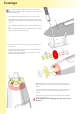
Fuselage i To use electric power in your Triple Neo the nose of the fuselage needs to be cut off with the help of a template. For the glider version skip building steps 1-6. 1 Glue together fuselage template from parts S1-S4. Leave to dry. Slide fuselage R0 into template as shown. Please note that there is a small bump on the underside of the fuselage which fits into template exactly. R1 Run a sharp knife around the fuselage as shown to mark the cut-off line.
i To complete the next building step you will need the collet prop adapter which is available as an accessory. Make sure the prop adapter fits the prop shaft of your motor (for Order-No. see page 2). 4 Remove installing tool S7 when epoxy glue has cured. Assemble the collet adapter with prop hub yoke and temporarily install the motor into the fuselage. Install collet adapter on motor shaft and tighten nut with your fingers.
9 Glue together balsa parts R21 and plywood parts R22 to form the tailplane support. R13 R21 7 Wrap 180 grit sandpaper around the carbon fuselage tube R13 and sand tailplane support to fit carbon tube. R22 R21 Note that edges of plywood parts must not be sanded down. See enlarged graphics for correct result. This will guarantee a perfect fit on the fuselage tube. Work carefully and glue support to fuselage tube with epoxy. Make sure it is absolutely straight and horizontal.
11 Slightly sand front end of carbon tube R13. Apply epoxy resin to oblong opening in former R8. Then glue plywood ring R14 to tube and former. The tube will automatically be aligned in a perfectly horizontal position by using the templates. Leave to cure. R13 R8 R14 Apply glue to tube and fuselage 12 Bring fuselage in a vertical position and apply epoxy resin to opening in fuselage around tube.
Tail Unit 1 A flat surface or building board is required to build the tail unit. Protect building board with cling film so that tailplane parts will not stick to the surface of the building board. Remove required parts from laser sheets and glue in place as shown. L6 L7 L8 L3 L2 L4 L8 L5 L7 L1 L6 L5 L4 L3 2 Use 1-mm-balsa to sheet the tail unit. Glue laser-cut sheeting material to either side of structure and weigh down evenly to avoid warping.
3 When sheetig material has dried completely, bevel off rear edge of tailplane to allow for sufficient control throw of elevator. L1 L9 L12 4 Glue reinforcements L12 to inner edges of elevator panels. 5 Build up fin and rudder in the same way.
R24 8 Lightly sand rear end of carbon tube and glue tailplane support to carbon tube with epoxy. Use template S10 for proper alignment. See graphics for correct position of tailplane support. Glue tail skid R24 into carbon tube with epoxy. A slot in template S10 will accommodate the skid. Make sure there is room for the bowden cables in the tube on either side of the tail skid. 9 Glue the fin to the tailplane and let dry.
10 Glue control horns L24 into rudder and elevator. L24 10 Rounf off front of triangular stock L25 and glue to either side of fin. Apply covering material to the tail unit and attach rudder and elevator with hinge tape or equivalent. L25 11 Slide bowden cables R25 into carbon tube on either side of tail skid R24. Glue bowden cable outers to skid with a drop of epoxy. R24 R25 12 Install and glue part R26 to fuselage end of carbon tube between bowden cable outers R25.
Section IV - Triple speed Wing Attention: Make sure you build a left and a right wing panel. In this section construction of one wing panel is described. Build the opposite wing panel accordingly. 1 Protect building board with cling film. Place two parts TS-01 on building board as shown and secure with pins. Glue spruce strip TS-02 (2 x 8 mm) to TS-01 and cut off flush with sheeting material on either side.
4 Place two-piece trailing edge sheeting TS-05 and TS-07 as well as aileron sheeting TS-06 in the jig as shown. TS-07 TS-06 TS-05 5 Fit ribs TS-09 to TS-25 in place in numerical order. Root rib TS-08 will be fitted at a later stage. Make sure you position ribs exactly at right angles in relation to spar, then glue in place. Note, that ribs are glued to spruce spar, main spar, trailing edge sheeting and aileron sheeting. Do not apply glue to front part of ribs between wing spar and leading edge position.
8 Cut to length upper spruce spar TS-02 (2 x 8 mm) and glue to ribs and main spar. Use suitable weigths to hold spar in place and leave to dry. TS-02 9 Glue in place aileron spar TS-28, aileron leading edge TS-29 as well as gussets TS-30 and TS-31. Insert servo tray TS-32 between ribs TS-16 and TS-17, flush with underside of ribs and against wing spar. Do not glue! Glue end stop TS-32.1 to both ribs and glue reinforcement TS-32.2 in place on aileron. TS-31 TS-32 TS-28 TS-32.1 TS-30 TS-29 TS-32.
11 Carefully sand surface of wing joiner sleeve TS-35 and insert in wing root. Insert wing joiner R-40 into sleeve and make sure it moves freely and without binding. Then remove R-40 and glue sleeve in place with epoxy mixed with glass fibres. Repeat for TS-35.1. Align magnet supports TS-46 and TS-47 with corresponding holes in rib TS-08, then glue to the inside of rib TS-08. TS-35 TS-46 TS-47 TS-35.1 12 Glue together wing root sheeting material TS-33 and TS-34, then glue to first two rib bays.
13 Remove wing from building board. Please handle with care and always place on an even surface, as the wing has no tortional stability at this time. Glue bottom sheeting material to ribs. For best results use thin CA. Also glue in place sheeting material to the underside of wing root. 14 Glue false leading edge TS-36 (balsa, 2 x 8 mm) to ribs and bottom sheeting. Sand flush with top of ribs after glue has dried. TS-36 15 Glue in place top sheeting TS-01 on ribs, spar and flase leading edge.
16 Cut off sheeting material flush with false leading edge then carefully sand sheeting material flush with false leading edge. Use a long sanding bar for best results. Then glue leading edge TS-37 (balsa, 3 x 8 mm) to false leading eding edge and sand to shape after glue has dried. TS-37 17 Make up wing tips from 3 parts TS-38 and secure with clamps until dry. TS-38 18 Sand sheeting material and spars flush with tip rib TS-25 and glue in place wing tip TS-38.
TS-39 19 Use a razor saw to cut out the aileron and carefully sand sheeting material flush with riblets on either side. Glue TS-39 to front of aileron and bevel off to allow for sufficient control throw. After covering attach aileron to wing with tape. Tip: If you do not want to use tape, you can bevel off top and bottom of TS-39 and use small hinges to attach the aileron to the wing.
Section V - Triple R.E.S. Wing Attention: Make sure you build a left and a right wing panel. In this section construction of one wing panel is described. Build the opposite wing panel accordingly. 1 Protect building board with cling film. Place two parts TR-01 on building board as shown and secure with pins. Glue spruce strip TR-02 (2 x 8 mm) to TR-01 and cut off flush with sheeting material on either side.
4 Fit ribs TR-07 to TR-15 in place in numerical order. Notches in Spar and trailing edge help to position the ribs correctly. Note, that ribs are glued to spruce spar, main spar and trailing edge sheeting TR-05. Do not apply glue to front part of ribs between wing spar and leading edge position. TR-15 Note: Root rib TR-06 will be fitted at a later stage together with TR-04. TR-04 determines the correct dihedral angle for the root rib.
7 Glue bottom sheeting material to ribs. For best results use thin CA. Also glue in place sheeting material to the underside of wing root. 8 Glue together wing root sheeting material TR-16 and TR-17, then glue to first rib bay on underside of wing. TR-16 TR-17 9 Place wing on building board and glue false leading edge TR-18 (balsa, 2 x 8 mm) to ribs and bottom sheeting. Sand flush with top of ribs after glue has dried.
10 Glue in place top sheeting TR-01 on ribs, spar and flase leading edge. Use suitable weights and tape to secure sheeting material until glue has dried completely. TR-01 TR-19 12 Sand sheeting material and spars flush with tip rib TR-15 and glue in place wing tip TR-20. The tip is made up of three individual parts. 11 Cut off sheeting material flush with false leading edge then carefully sand sheeting material flush with false leading edge. Use a long sanding bar for best results.
Section VI - Triple thermic Wing Attention: Make sure you build a left and a right wing panel. In this section construction of one wing panel is described. Build the opposite wing panel accordingly. 1 Protect building board with cling film. Place two parts TT-01 on building board as shown and secure with pins. Glue spruce strip TT-02 (2 x 8 mm) to TT-01 and cut off flush with sheeting material on either side.
4 Fit ribs TT-09 to TS-23 in place in numerical order. Glue in place aileron riblets TT-24 and TT-25. Make sure you position ribs exactly at right angles in relation to spar, then glue in place. Note, that ribs are glued to spruce spar, main spar, trailing edge sheeting and aileron sheeting. Do not apply glue to front part of ribs between wing spar and leading edge position. Root rib TT-08 will be fitted at a later stage.
7 Glue in place aileron spar TT-26, aileron leading edge TT-27 as well as gussets TT-28 and TT-29. Insert servo tray TT-30 between ribs TT-14 and TT-15 flush with underside of ribs and against wing spar. Do not glue! Glue end stop TT-30.1 to both ribs and glue reinforcement TT-30.2 in place on aileron. TT-29 TT-26 TT-15 TT-30.1 TT-30 TT-14 TT-27 TT-28 TT-30.2 Glue together servo frames TT-30.3 and TT-30.4 as shown, and glue to spar and ribs. Make sure that hole for servo lead is not obstructed.
9 Glue together wing root sheeting material TT-31 and TT-23, then glue to first rib bay. TT-31 TT-32 10 Remove wing from building board. Please handle with care and always place on an even surface, as the wing has no tortional stability at this time. Glue bottom sheeting material to ribs. For best results use thin CA. Also glue in place sheeting material to the underside of wing root.
11 Place wing on building board and glue false leading edge TT-33 (balsa, 2 x 8 mm) to ribs and bottom sheeting. Sand flush with top of ribs after glue has dried. TT-33 12 Glue in place top sheeting TT-01 on ribs, spar and false leading edge. Use suitable weights and tape to secure sheeting material until glue has dried completely. Cut off sheeting material flush with false leading edge then carefully sand sheeting material flush with false leading edge. Use a long sanding bar for best results.
14 Make up wing tips from 3 parts TT-35 and secure with clamps until dry. Sand sheeting material and spars flush with tip rib TT-23 and glue in place wing tip TT-35. Then sand wing tip to fit planform of wing and shape of wing section. TT-35 15 Use a razor saw to cut out the aileron and carefully sand sheeting material flush with riblets on either side. Glue TT36 to front of aileron and bevel off to allow for sufficient control throw. After covering attach aileron to wing with tape.
Section VII - R.E.S. and thermic Centre Section Attention: Make sure you build a left and a right wing panel. In this section construction of one wing panel is described. Build the opposite wing panel accordingly. 1 Protect building board with cling film. Place two parts TM-01 on building board as shown and secure with pins. Glue spruce strip TM-02 (3 x 8 mm) to TM-01 and cut off flush with sheeting material on either side.
4 Fit ribs TM-08 to TM-17 in place. Make sure you position ribs exactly at right angles in relation to spar, then glue in place. Note, that ribs are glued to spruce spar, main spar and trailing edge sheeting. Do not apply glue to front part of ribs between wing spar and leading edge position. TM-17 Note: Root rib TM-07 will be fitted at a later stage together with TM-05. TM-05 determines the correct dihedral angle for the root rib.
7 Glue supports TM-18 into ribs at the spoiler position and TM-18 glue sheeting panel TM-19 in place. TM-19 Note that sheeting is centred on supports and ribs which act as an end stop for the spoiler. 8 Remove wing from jig. Slightly bevel the last 3 mm of trailing edge TM-22 sheeting to establish a good contact surface for gluing. Then glue in place top sheeting TM-06. Glue together wing root sheeting material TM-122 and TM-23, then glue to outer rib bays.
10 Glue together wing root sheeting material TM-22 and TM-23, then glue to first rib bay on either side of wing. TM-22 TM-23 11 Place wing on building board and glue false leading edge TM-24 (balsa, 2 x 8 mm) to ribs and bottom sheeting. Sand flush with top of ribs after glue has dried. TM-24 12 Glue in place top sheeting TM-01 on ribs, spar and false leading edge. Use suitable weights and tape to secure sheeting material until glue has dried completely.
13 Sand sheeting material flush with false leading edge. Use a long sanding bar for best results. Glue leading edge TM-25 (balsa, 3 x 8 mm) to false leading eding edge and sand to shape after glue has dried. TM-25 TM-26 14 Glue control horn TM-27 to spoiler TM-26. Make sure to build a left and a right spoiler! File a notch for control horn TM-27 and fit spoiler in place. When wing is has been covered, attach spoiler to wing with tape. TM-27 A final sanding will make the inner wing panel ready to cover.
Completing the Model 1 Install servos in fuselage. Install connectors R28 on control horns and connect piano wires. Bend wires R27 to fit connectors on control horns and make sure they move freely and without binding. See graphics for details. R28 R27 R27 R28 2 Install radio equipment and battery and connect servos. R30 Secure battery with hook and loop tape on battery tray. This will help you adjust the centre of gravity by moving battery to the correct position.
4 Triple Neo speed und thermic: For aileron control use servos with a maximum width of 11,5 mm. Install connector in outer-most position on servo arm and move servo arm to neutral position. Place servo on servo tray. Establish and mark position of aileron horn. Cut piano wire TS-43 / TT-38 to length and make a Z-bend at one end. Glue servo in place and retract servo arm into wing before covering.
Parts list Triple NEO fuselage + tail Parts lists No S-1 S-2 S-3 S-4 S-5 S-6 S-7 S-8 S-9 S-10 R-1 R-2 R-3 R-4 R-5 R-6 R-7 R-8 R-9 R-10 R-11 R-12 R-13 R-14 R-15 R-16 R-17 R-18 R-19 R-20 R-21 R-22 R-23 R-24 R-25 R-26 R-27 R-28 R-29 R-30 L-1 L-2 L-3 L-4 L-5 L-6 L-7 L-8 L-9 L-10 L-11 L-12 L-13 L-14 L-15 L-16 L-17 L-18 L-19 L-20 L-21 L-22 L-23 L-24 L-25 Item template motor mount template motor mount template motor mount template motor mount spacer screw installation tool nut template template fuselage motor mo
Parts list wings „speed“ P q0 VU/23 VU/24 VU/25 VU/26 VU/27 VU/28 VU/29 VU/2: VU/2; VU/32 VU/33 VU/34 VU/35 VU/36 VU/37 VU/38 VU/39 VU/3: VU/3; VU/42 VU/43 VU/44 VU/45 VU/46 VU/47 VU/48 VU/49 VU/4: VU/4; VU/52 VU/53 VU/54 VU/5403 VU/5404 VU/5405 VU/5406 VU/55 VU/56 VU/57 VU/5703 VU/58 VU/59 VU/5: VU/5; VU/62 VU/63 VU/64 VU/65 VU/68 VU/69 Item sheeting spruce spar main spar wing joiner brace trailing edge sheeting aileron sheeting trailing edge sheeting root rib wing rib wing rib wing rib wing rib wing rib
parts list wings „R.E.S.
parts list wings „thermic“ P q0 VO /23 VO /24 VO /25 VO /26 VO /27 VO /28 VO /29 VO /2: VO /2; VO /32 VO /33 VO /34 VO /35 VO /36 VO /37 VO /38 VO /39 VO /3: VO /3; VO /42 VO /43 VO /4303 VO /44 VO /45 VO /46 VO /47 VO /48 VO /49 VO /4: VO /4; VO /52 VO /53 VO /54 VO /55 VO /56 VV/23 VV/24 VV/25 VV/26 VV/27 VV/28 VV/29 VV/2: VV/2; VV/32 VV/33 VV/34 VV/35 VV/36 VV/37 VV/38 VV/39 VV/3: VV/3; VV/42 VV/43 VV/44 VV/45 VV/46 VV/47 VV/48 VV/49 VV/4: VV/4; VV/52 VV/5203 VV/5204 VV/5205 VV/5206 VV/53 VV/54 VV/55 VV
More great model kits... SkyMaxx 1370/00 wingpsan 1.550 mm Laser-Cut-kit incl. steerable nose-wheel and depron building jig Fournier RF-4D 1355/01 wingspan 2.800 mm Laser-Cut kit with GRP fuselage and depron building jig SHK 1125/01 wingspan 4.000 mm Lasercut kit with GRP fuselage and depron building jig can be found on www.aero-naut.com aero-naut Modellbau Stuttgarter Strasse 18-22 D-72766 Reutlingen Germany www.aero-naut.