
Instructions / Assembly


8
Ⅳ
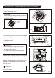
Fig.14
3.
Screw from
Parts Bag
Attach cable clamp to Knockout
Plate.Knockout Plate mounts to
outside of Housing and may be
positioned as desired.
Connect
wires
Ⅱ
Ⅲ
Ⅰ
INSTALLATION II(RETROFIT)
Put the folded bracket assembly into ceiling hole,
then follow step 3-4 of Installation
I (NEW
CONSTRUCTION page 5) to complete the extra
spacebracket installation. (Fig.12)
2.
1.
Screws
(ST4x30)
Unit:inches(mm)
Unit: inches (mm)
Fig.12
Fig.13
A
B
screws
(ST4x20)
10 3/5(270)
10 3/5(270)
Follow step 4 of Installation I (NEW
CONSTRUCTION page 6) to complete the
adaptor installation. (Fig.13)
Install a circular duct and secure with clamps
or ties and seal with mastic or approved foil tape.
A 4", 5", or 6"circular duct is needed to connect
to relevant part of adaptor. (Fig.13)
Remove the knock-out plate and secure conduit
or wire protector nut to knock-out hole. (Fig.14)
Refer to wiring diagram on page 4.
Using UL approved wire nuts, connect house power
wires to the ventilating fan wires (Fig.14), then
attach it to fan body.
Follow all the local eletrical safety codes as well
as the National Electrical Code (NEC).
IMPORTANT: