Installation Guide For Aero-Stream® Septic Tank Riser Kits For additional assistance please contact us at: Technical Support (Toll Free) 877-254-7093 OR info@aero-stream.com P/N 102368 Rev.
Critical Safety Warning: Always securely attach Cover to Riser by installing and tightening the (4) screws using the appropriate driver tool. Cover must be checked after each tank servicing. Cover must be inspected regularly for damage and security. The secondary safety barrier must be securely fastened in place at all times. The safety barrier must only be removed to gain entry into the tank by a properly credentialed professional donning appropriate safety gear.
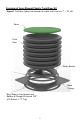
Overview of Aero-Stream® Septic Tank Riser Kit Figure 1 illustrates typical construction of septic tank riser kits 7” – 19” tall.
Figure 2 illustrates typical construction of septic tank riser kits 23” – 38” tall.
Figure 3 illustrates typical construction of septic tank riser kits 41” – 50” tall.
The Installation Process: Installation must be performed by person possessing mechanical competence. 1.) Assemble riser flange by interlocking the four sections as shown in Fig.
2.) With the white tape upward, apply approximately 77” of butyl sealant rope around the perimeter of the adapter flange where the riser pipe will meet the flange (Fig.5). Cut off remaining butyl sealant & set aside for step 11. Overlap and knead the ends of the butyl rope together to ensure a water-tight seal. Butyl Sealant Figure 5 3.) Remove the white tape from the sealant rope and discard the tape. 4.) Center the riser pipe on the adapter flange so the gap is even all of the way around.
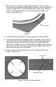
6.) Install four (4) provided #12 x ¾” screws into mounting dimples to attach the adapter flange to the riser pipe. Drive the screws until the head makes contact with the adapter flange & slightly compresses the flange (Fig 7.) & (Fig 8). There should be a visible gap (approximately 1/2”) between base flange & pipe once installed. OPTIONAL: Mounting dimples can be pre-drilled with 1/8” bit to facilitate screw installation.
How to Install the Safety Barrier: 7.) Locate the four mounting tabs on the safety barrier (Fig. 9). Insert the safety barrier into the locking tabs on base flange (Fig 8), (Fig. 9) & (Fig. 10). Barrier mounting tabs may require individual adjustment and alignment while seating the barrier onto flange. Note the barrier can bend slightly to accommodate for manufacturing tolerances. Once positioned, apply downward pressure to center of barrier. Mounting Tab Figure 9 Figure 10: Inserting Safety Barrier 8.
Mounting the Riser Kit: 10.) Expose and clean a 32” x 32” square area on the top of the septic tank centered on the clean-out opening on the tank. Figure 11 11.) With the white tape upward, apply the remaining butyl sealant rope around the groove on the bottom of the adapter flange; overlapping and kneading the ends of the butyl rope together (Fig. 12). Remove the white tape from the sealant rope and discard the tape.
13.) Drill (4) 5/32” diameter holes through the four corners of the adapter flange (Fig. 13) at least 2” deep into the tank. If the tank is made of concrete, use a carbide tip masonry bit. Warning: Ensure holes are free of debris otherwise fastener failure may occur 14.) Fasten the base plate to the tank using four (4) provided 3/16” X 1 ¾” blue Tapcon screws (Fig 13). Figure 13: Mounting Base Flange 15.