
Instructions / Assembly

6
For Pipe Sections 6”-18” Skip to Step 5
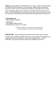
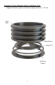
Pipe Sections 22”-50”:
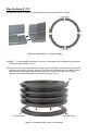
4.) Stack pipe sections as shown in Fig. 2 & 3. Center riser pipe on the connector flange of
lower pipe section so the gap is even all of the way around. It’s recommended to seal the
gap between the pipe sections using multi-purpose silicone or caulk.
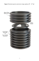
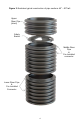
5.) Locate the four (4) mounting dimples on the inside perimeter of the connector flange (Fig.6).
Install four (4) screws into mounting dimples to attach the connector flange to the riser pipe.
Drive the screws until the head makes contact with the connector flange & slightly
compresses the flange. A ½” gap should be present between the connector & pipe.
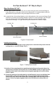
Installing Safety Barrier:
6.) Locate the four mounting tabs on the safety barrier. Insert the safety barrier into the
locking tabs on connector flange. (Fig 7)
7.) Confirm all four mounting tabs are positioned with all four locking tabs. Rotate the
safety barrier clockwise, the direction the “LOCK ARROW” points. A slight rap with
the palm of the hands in the safety barrier triangular openings will seat the safety
barrier in place.
8.) Grasp the openings of the safety barrier and pull upward. It must not dislodge from
the assembly. If any of the mounting tabs are not engaged with the locking tabs,
remove the safety barrier and repeat step 6 through step 8 until the safety barrier is
secure. Failure to properly engage safety barrier will defeat the safety feature of
device!
Figure 7: Safety Barrier Install
Screw Installed
Mounting Tab
Mounting dimple
Locking Tab
Locking Tab
Figure 6: Screw Install