
User Manual


50289-BDA
USE OR DISCLOSURE OF DATA CONTAINED ON THIS PAGE IS SUBJECT TO THE
RESTRICTION ON THE TITLE PAGE OF THIS MANUAL
10
AC POWER CONNECTION
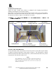
Install AC power conduit. Each cabinet is configured with clamping-ring hardware
suitable for attachment of ½” electrical conduit.
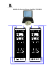
Each cabinet is fitted with an electrical junction box inside at the top rear of the cabinet.
Remove the cover plate and connect the AC source lines to the appropriate terminals in
the junction box. Refer to figure 1. Re-install the cover plate.
Figure 1. Thermostat & Electrical Power InFigure 1. Thermostat & Electrical Power In
stallationstallation
ELECTRICAL
JUNCTION BOX
THERMOSTAT MAIN AC POWER
OUTLETS FOR CABINET
COOLING FAN
POWER SWITCH
BATTERY
CONNECTION
CABINET CEILING INCOMING
AC SERVICE CONDUIT
SETTING THE THERMOSTATS
Set the thermostat inside each cabinet for 90-95ºF (32-35°C). This will keep the cabinet
at optimal operating temperatures. Refer again to Figure 1. The Thermostat is marked
with three dots between 80ºF and 130ºF(27-54°C). Turn the thermostat dial so the pointer
is just past the first dot above 80ºF (27°C).
NOTE
THE THERMOSTATS MAY BE ADJUSTED AFTER INSTALLATION BY
REMOVING THE GRILL AND FILTER ON THE TOP OF EACH CABINET. THE
USER CAN THEN REACH THROUGH THE ACCESS HOLE TO ADJUST THE
THERMOSTAT SETTINGS.