
User guide

8 GR-LEON4-ITX Development Board
Quick Start Guide
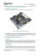
only provides PIN headers with the receive and transmit lines for the serial terminal it is
recommended that a monitor, keyboard and mouse is attached to the board. According the
normal conventions for the PS/2 interface, the top connector (green) is the Mouse interface
and the bottom connector (purple) is the Keyboard interface. If using a USB keyboard and
mouse the devices should be connected via a USB hub and the USB memory stick should
be directly connected to one of the board's USB ports.
The connected monitor must support DVI-A output, the board can also be connected to a
monitor using a DVI-to-VGA adapter.
It is recommended, but not required, to connect the board to a Ethernet network where it can
receive an IP address via DHCP and access the Internet. This will allow system software to
automatically set the system date and time. If an Ethernet cable is attached it should be
connected to the first Ethernet port (the lower port).
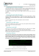
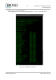
Booting Linux
The bootloader will start Linux when the power adapter is attached to the board. Please skip
to section 3 for usage instructions. Section 5.1 contains transcripts of the output that should
be shown on the monitor during the boot process.
2.3 Connecting with the GRMON debug monitor
Overview
GRMON is a competent debug monitor that is used to debug GRLIB/LEON systems. The
GR-LEON4-ITX board has a number of debug interfaces that are all supported by GRMON.
Note: If you intend to use GRMON to work with the board it is recommended to clear the
SPI boot PROM as described in section 4.5 .
Pre-requisites
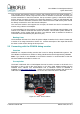
The board is delivered with a JTAG adapter that can be used to connect to the board. For a
description of how to set up the JTAG device, or for other JTAG adapters please see the
GRMON User's Manual. The documentation and a evaluation version of GRMON is
available from http://www.gaisler.com. Unless you will be loading software that will use the
USB Flash stick, it is recommended to not connect the USB Flash stick to the board.
© Aeroflex Gaisler AB March 2013, Rev. 0.3
Figure 2-2: User JTAG headers