
User manual

14 GR-LEON4-ITX Development Board
User Manual
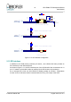
The host interfaces include a MIC2025USB power switch component, controlled to provide
5V power output to the Dual USB-A style connector on the board.
Please refer to the device data sheet of the ISP1504A device for further information.
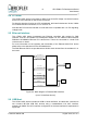
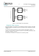
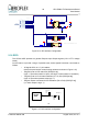
2.7 USB Device
The LEON4 ASIC device also includes USB 2.0 Device interface, also connected to an
ISP1504 USB PHY device on the board, with a 8 bit ULPI interface, operating at 60MHz.
The interface configuration is similar to that represented in Figure 2-6, except that a
USB-B device connector is installed on the board, and no power switch is required for this
interface
2.8 USB Debug Communication Link
A second USB Device link is provided on the board (Connector J6), which is dedicated for
the USB Debug Communication link as described in section 2.17 and section 3.
Note that, to enable this interface, it is necessary that the GPIO43 pin is pulled high at power
on of the board.
This can be achieved by inserting a jumper on the pins 17-18 of the header connector J10.
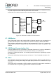
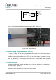
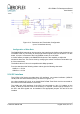
2.9 Video
The GR-LEON4-ITX board incorporates an Chrontel CH7301C display controller device for
DVI interfaces, providing both Analog and Digital display interfaces on a standard DVI-I style
connector.
The LEON4 ASIC incorporates a SVGA controller core with DVI support which interfaces to
the controller device to provide a graphical video interface to the board.
© Aeroflex Gaisler AB August 2010, Rev. 0.3
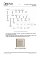
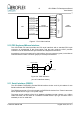
Figure 2-6: USB Host Controller PHYsical Interface
ISP1504A
USB PHY
ISP1504A
USB PHY
ASIC
ASIC
NEXT
DATA[7..0]
USB
INTERFACE
XTAL
19.2MHz
XTAL
19.2MHz
DP
DM
USB A
USB A
STP
DIR
CLK (60MHz)
RESETN_N
POWER
SWITCH
POWER
SWITCH
ENABLE