
User manual

16 GR-LEON4-ITX Development Board
User Manual
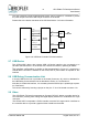
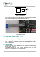
The included ribbon cables providing a DE-9 connector should be connected as shown in
figure 2-10 (the red stripe should be toward the label UART-1/UART-2).
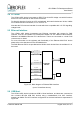
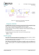
2.12 Serial Debug Support Interface (LVTTL)
A 10 pin 0.1” header on the board (J12) provides connections to the serial Debug Support
Unit signals DSURX (receive) and DSUTX (transmit).
Note that these voltage levels are 3.3V LVTTL and not RS232 levels. If you wish to connect
to this interface would be necessary use an adapter circuit to convert the signals to RS232
levels, or alternatively, a converter chip such as the FTDI FT232 could be used to provide a
Serial to USB conversion.
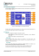
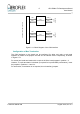
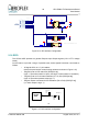
2.13 CAN Interface
The board provides the electrical interfaces for two CAN bus interfaces, as represented in
the block diagram, Figure 2-11.
The CAN bus transceiver IC's on this board are SN65HVD230 devices from Texas
Instruments which operate from a single +3.3V power supply.
© Aeroflex Gaisler AB August 2010, Rev. 0.3
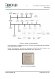
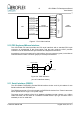
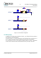
Figure 2-9: Serial interface
ASIC
RS232
INTERFACE
SUB-D 9 pin
Female
RS232
DRIVER/
RECEIVERS
TXD
RXD
Figure 2-10: Serial interface