
User manual

18 GR-LEON4-ITX Development Board
User Manual
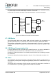
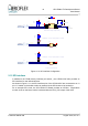
Configuration of Slew Rate
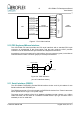
The SN65HVD230 transceiver device used on the board has the facility to set the device into
STANDBY mode, by connecting an active high external signal to pin 8 of the device. On this
board, this pin is connected to the CAN_ENable contorl pin of the ASIC.
A further feature provided by the SN65HVD230 device is the capability to adjust the
transceiver slew rate. This can be done by modifying the values of resistors connected to pin
8 of the transceivers.
The default value of 0 ohms is compatible with 1Mbps operation.
From the data sheet the following resistor values give the following slew rates:
10kOhm => 15V/us
100kOhm => 2V/us
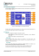
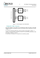
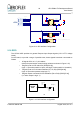
2.14 I2C interface
The LEON4 ASIC device provides three I2C interfaces, two master interfaces (I2CM0 &
I2CM1) and one slave interface (I2CS), as shown in Figure 2-13.
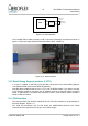
As a demonstration I2C circuit, an on-board DS1672 Real-Time Clock circuit is connected on
the board to the I2CM0 interface of the ASIC.
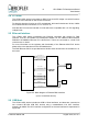
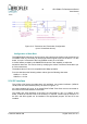
The I2CM1 and I2CS interfaces of the ASIC are connected to 4 pin 0.1” headers on the
board, to allow an external circuit to be hooked-up. If required, 10kOhm pull-up resistors on
the SCL and SDA signals can be installed if the appropriate jumpers JP9 and JP10 are
installed.
© Aeroflex Gaisler AB August 2010, Rev. 0.3
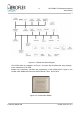
Figure 2-12: Transceiver and Termination Configuration
(one of 2 interfaces shown)