OPERATION MANUAL NAV 2000R SIGNAL GENERATOR MANUAL NUMBER: 06-0520-5A (Hard Copy) E6-0520-5A (CD-ROM) REVISION: 0 DATE: 07/26/2007 WARNING: INFORMATION SUBJECT TO EXPORT CONTROL LAWS This document contains controlled technology or technical data under the jurisdiction of the Export Administration Regulations (EAR), 15 CFR 730-774. It cannot be transferred to any foreign third party without the specific prior approval of the U.S. Department of Commerce Bureau of Industry and Security (BIS).
ELECTROSTATIC DISCHARGE GENERAL WARNINGS FOR ALL EQUIPMENT CAUTION: THIS EQUIPMENT MAY CONTAIN ELECTROSTATIC DISCHARGE (ESD) SENSITIVE COMPONENTS. TO PREVENT ESD SENSITIVE EQUIPMENT FROM POSSIBLE DAMAGE, OBSERVE THE FOLLOWING PRECAUTIONS WHEN HANDLING ANY ESD SENSITIVE COMPONENTS, OR UNITS CONTAINING ESD SENSITIVE COMPONENTS: a.
Aeroflex Operation Manual REVISION HISTORY BY DRAWING NUMBER MANUAL: NAV 2000R Signal Generator REVISION: 0 – July 26, 2007 DRAWING NO. REV. _LEVEL DRAWING NO. REV.
Aeroflex Operation Manual Safety and Regulatory Information Review this product and related documentation to familiarize yourself with safety markings and instructions before you operate this equipment. WARNING The WARNING notice denotes a hazard. It calls attention to a procedure, practice, or the like, that, if not correctly performed or adhered to, could result in personal injury. Do not proceed beyond a WARNING notice until the indicated conditions are fully understood and met.
Aeroflex Operation Manual Protective conductor terminal. This symbol indicates the protective ground (earth) terminal. Frame or chassis terminal. This symbol indicates the frame or chassis terminal for connection to ground. Equipotentiality. This symbol indicates an equipotentiality terminal. On (Supply). This symbol indicates that the power line switch is ON. Off (Supply). This symbol indicates that the power line switch is OFF. Standby. This symbol indicates that the power line switch is in STANDBY.
Aeroflex Operation Manual Warnings WARNING Do not use the equipment in a manner not specified in this manual! WARNING Equipment should only be serviced by authorized personnel. WARNING To avoid fire hazard, use only a fuse identical in type, voltage rating, and current rating as specified on the fuse rating label and/or in the manual. Proper Power Cord Use only the power cord and connector appropriate for the voltage and plug configuration in your country.
Aeroflex Operation Manual WARNING TO SERVICE PERSONNEL Ensure that power is disconnected before removal of any covers. WARNING The Power switch on the Front Panel is not the mains disconnect. Mains disconnect is accomplished by disconnecting the detachable power supply cord at the appliance coupler or at the mains plug. Ensure the power cord is easily accessible and removable, in the event of an emergency, which requires immediate disconnection. 5 1. 2. 3. 4. 5. 6. 7.
Aeroflex Operation Manual TABLE OF CONTENTS SECTION I GENERAL INFORMATION SECTION 1.1 1.2 1.3 1.4 1.5 1.6 1.6 PAGE NUMBER GENERAL INFORMATION .................................................................. 1-1 EQUIPMENT DESCRIPTION .............................................................. 1-1 TECHNICAL CHARACTERISTICS ...................................................... 1-1 UNITS AND ACCESSORIES SUPPLIED ............................................ 1-6 UNITS AND ACCESSORIES REQUIRED ............
Aeroflex Operation Manual SECTION III OPERATION (Con't) SECTION 3.5.18 3.6 3.6.1 3.6.2 3.7 3.8 PAGE NUMBER STORING & RECALLING SETUPS..................................................... 3-24 REMOTE USER INTERFACE.............................................................. 3-24 GPIB REMOTE INTERFACE DESCRIPTION ..................................... 3-24 COMMAND LIST .................................................................................. 3-25 USING THE EXTERNAL AUDIO INPUT.....................
Aeroflex Operation Manual SECTION IV THEORY OF OPERATION (Con't) SECTION 4.5.12 4.5.13 4.5.14 4.5.15 4.5.16 4.5.17 4.5.18 4.5.19 4.5.20 4.5.21 4.5.22 4.5.23 4.6 4.7 4.7.1 4.7.2 4.7.3 4.7.4 4.8 PAGE NUMBER VOLTAGE REFERENCE ..................................................................... 4-17 DETECTED AUDIO HI/LO INDICATION ............................................. 4-18 PROGRAMMABLE STEP ATTENUATOR CONTROL ........................ 4-18 RF MODUALTOR BOARD ...........................................
Aeroflex Operation Manual SECTION I GENERAL INFORMATION 1.1 GENERAL INFORMATION The Aeroflex NAV 2000R generates ADF, MARKER BEACON, HF/VHF, COM and SELCAL signals for test applications. 1.2 EQUIPMENT DESCRIPTION The NAV 2000R VOR/ILS/COM Signal Generator contains necessary hardware and firmware to provide modulated RF signals to verify operation of VOR navigational, ILS (Glideslope, Localizer, and Marker Beacon), and COM communications LRU systems for aircraft.
Aeroflex Operation Manual Mass (Weight) 61.2 kg (135 lbs.) Ventilation Requirements Keep the ventilation openings clear. IEC Overvoltage Category II Pollution Degree 1 Equipment Meets These Listed Standards EN 61010-1 (IEC 61010-1) EN 61328 EN 61326 Class A Cables and Wires 1.
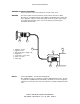
Aeroflex Operation Manual Mains Input Selection Selection of mains input range is done at the appliance inlet (A1FL1) on the back panel. For 115 V ac ± 10%, set the selector to the 115 V position. For 230 V ac ± 10%, set the selector to the 230 V position. Either selection will accept 50 or 60 Hz. To change the voltage selection: 1. Disconnect the appliance coupler. 2. With a flat blade screwdriver, or similar tool, open the cover. 3.
NAV 2000R Carrier: Aeroflex Operation Manual (TYPICAL) NAV 2000R 333 MHz Carrier: +0 −10 −20 +0 −10 −20 −30 −40 −30 −40 −50 −60 −70 −80 −90 −100 −110 −120 −130 −50 −60 −70 −80 −90 −100 −110 −120 −130 −140 10 100 1K 10K 100K −140 10 single side band phase noise (dBc/Hz) vs.
Aeroflex Operation Manual Amplitude Modulation Range (per tone) 1020 Hz IDENT 30 Hz variable 9960 Hz Resolution Overall accuracy Tone distortion (RF at default) Total VOR demodulated error LOCALIZER mode Modulation tones Frequencies Frequency accuracy Frequency adjustment Range Distortion (audio) 90/150 Hz phase Fixed Variable Resolution Variable Accuracy Amplitude modulation Range (per tone) 90 and 150 Hz Default Variable 1020 Hz Default Variable Accuracy (sum of all tones) Tone distortion (RF at default)
Aeroflex Operation Manual 90/150 Hz phase Fixed Variable resolution Variable accuracy Amplitude modulation Range (per tone) 90 and 150 Hz Default Variable Accuracy (sum of all tones) Tone distortion (RF at default) DDM Default Selectable settings Variable range Total system error (audio + modulation) 0.0 ± 0.01 degree 0.01 degree ± 0.05 degrees total % mod not to exceed 99% 40% 0 to 99% in 0.01% increments ± 2% of setting for 10% to 95% 2% maximum 0.000 DDM 0.000, 0.045, 0.091, 0.175, 0.400 DDM 0.
Aeroflex Operation Manual COMM Modulation tones (two tones selectable) Preset Variable Frequency accuracy Distortion (audio, 10 Hz to 10 kHz) Amplitude modulation Range Preset @ 1000 Hz Variable 10 to 18 kHz Accuracy External modulation Input impedance Maximum modulation depth Modulation distortion Modulation bandwidth Input level 1000 Hz and 2000 Hz 10 Hz to 18 kHz (0.1 Hz increments) ± 0.005% < 0.1% THD total % mod not to exceed 99% 30% 0 to 99% in 0.
Aeroflex Operation Manual 1.6 OPTIONAL EQUIPMENT ITEM DESCRIPTION TYPE 1 Extender Board JPN 20-5760-00 1.7 SERVICE INFORMATION If you have any questions regarding service, you may contact the factory at the address listed below: Aeroflex 400 New Century Parkway New Century, KS 66031 Phone: (913) 764-2452 Fax: (913) 782-5104 http://www.aeroflex.com NAV 2000R SIGNAL GENERATOR - REV.
Aeroflex Operation Manual SECTION II INSTALLATION 2.1 GENERAL INFORMATION This section contains information relating to the unpacking, inspection, and installation of the Aeroflex NAV 2000R VOR/ILS/COM Generator. 2.2 UNPACKING AND INSPECTION OF EQUIPMENT Exercise extreme care when unpacking the unit and accessories. Make a visual inspection of the NAV 2000R for evidence of damage incurred during shipment. If a claim for damage is to be filed, save the shipping container to substantiate the claim.
Aeroflex Operation Manual SECTION III OPERATION 3.1 GENERAL INFORMATION This Section describes how to operate the NAV 2000R VOR/ILS/COM generator. It contains information for an initial inspection, general operating information, and local and remote operation. The NAV 2000R can be operated using either the local user interface or the remote user interface. The local user interface uses the front panel keypads and display. The remote interface uses a General Purpose Interface Bus (GPIB).
Aeroflex Operation Manual 3.3 REAR PANEL DESCRIPTION Figure 3-2 shows the NAV 2000R rear panel. Shown on the Figure are the modules, external modulation input, audio output, power connection, and GPIB bus connector. FIGURE 3-2: REAR PANEL 3.4 POWER UP PROCEDURE Before turning on the power to the NAV 2000R, ensure that the proper mains power is applied. Configure the unit for the input voltage to be used. To turn on the NAV 2000R, press the power button located at the bottom left corner of the front panel.
Aeroflex Operation Manual 3.5.1 NAV 2000R MODES The NAV 2000R local operation is menu driven through the use of mode menu pages. There are six generator modes and three utility modes. Each top level generator mode menu is accessed by pressing the corresponding mode menu select key. With the exception of G/S, the LOC/GS key toggles between LOC and G/S modes. These are aligned vertically and to the right of the display.
Aeroflex Operation Manual DISPLAY REGION: Status Line The status line enunciates certain NAV 2000R status conditions by using status flags. These flags are made from grouped alphanumeric characters. In some cases the annunciation involves flashing to attract attention. The flags, and their description, are detailed in this section. EDIT ENUNCIATOR The EDIT flag is enunciated whenever the user is editing a field.
Aeroflex Operation Manual To display the utility menu, any one of four generator mode keys [VOR, ADF, MKR, or COM] is pressed and held down for two seconds. The external modulation (EMM) mode and the calibration (CAL) mode can be entered from the utility menu by selecting the corresponding option on the menu. Pressing the number of the utility menu item will immediately select the menu option.
Aeroflex Operation Manual 3.5.4.2 ENTERING NUMERIC FIELD VALUES WITH THE KEYPAD Numeric field values can be entered directly using the numeric keypad. To modify a numeric field with the numeric keypad the field is first selected using the cursor keys. The entry begins with a depression of the numeric keypad digit. The previous numeric field value will blank and the new numeric digit, the one which caused the edit entry, will be placed right justified.
Aeroflex Operation Manual 3.5.4.5 RF LEVEL ENTRY Most all of the modes have an RF level control bubble associated with them. This field allows the RF level to be programmed. The RF level may be programmed with 1/10th dBm resolution using either dBm or uV/mV units. DBm numbers are entered using the ENT key. Microvolts and millivolt numbers may be entered using the uV and mV keys (STO/RCL) respectively.
Aeroflex Operation Manual AUDIO Selecting the audio control mode field places the NAV 2000R into VOR audio control mode. The audio control mode, designated as the "VORa" mode, commands the NAV 2000R to allow the VOR audio composite output to be varied. Within this mode, RF control is not allowed and the RF attenuator is fixed for a minimum output level of -127 dBm. Also, no identification coding is allowed.
Aeroflex Operation Manual IDENT MODE Allows the user to specify how the identification tone is to be modulated. This is a toggle type field containing three valid options: OFF, CODE, and TONE. A selection of OFF, the default setting, commands the NAV 2000R to force the percent of modulation to 0%. A selection of CODE, causes the NAV 2000R to Morse code modulate using the specified identification string. A selection of TONE, commands the NAV 2000R to modulate a steady tone.
Aeroflex Operation Manual 3.5.6 VOR AUDIO CONTROL MODE (VORa) FIELD DEFINITION The VOR audio control mode, VORa, is entered by pressing and releasing the SEL key while the AUDIO control mode field, on VOR page 1, is selected. This mode allows the user to specify the NAV 2000R audio output signal level using volts RMS. No RF level control is allowed while within this mode of operation. COMPOSITE AUDIO CONTROL: AUDIO LEVEL This field allows the audio signal level to be changed.
Aeroflex Operation Manual DDM Programs the %MOD of the 90 and 150 Hz tones. The valid entry range for this field is from .000 to .400 DDM (Difference in Depth of Modulation) with .001 resolution. The NAV 2000R computes the percent of modulation ratio between the 90 and 150 Hz required to produce the commanded DDM. The percent of modulation of each tone will be set to the proper ratio forcing both tones to total the standard modulation of 40%. The default value for this field is .
Aeroflex Operation Manual 90 Hz %MOD Programs the modulation percentage of 90 Hz tone. This is a numeric field type and is programmable from 0 to 99% in 0.01% steps. The default for this field is 20%. The "VALUE LIMITED TO MAXIMUM" error is displayed if a 90 Hz modulation percentage causes the total modulation percentage, the sum of percent modulation of the 90 Hz, 150 Hz, and the ident tone, to exceed 99%.
Aeroflex Operation Manual IDENT MODE The ident mode field selects the identification tone modulation method. This is a toggle field containing three valid options: OFF, CODE, and TONE. A selection of OFF, the default setting, commands the unit to force the percent of modulation to 0%. Selecting CODE, causes the unit to Morse code modulate the specified identification string. And a selection of TONE, commands the NAV 2000R to modulate a 1020 Hz tone.
Aeroflex Operation Manual DDM Programs the modulation percentage of the 90 and 150 Hz tones. The valid entry range for this field is from .000 to .400 DDM (Difference in Depth of Modulation) in .001 steps. The NAV 2000R computes the percent of modulation ratio between the 90 and 150 Hz tones required to produce the commanded DDM. When a valid Localizer DDM "hot" key is pressed the DDM will automatically be accepted.
Aeroflex Operation Manual DDM Programs the modulation percentage of the 90 and 150 Hz tones. The valid range for this field is from .000 to .800 DDM in .001 steps. The NAV 2000R computes the percent of modulation ratio between the 90 and 150 Hz tones required to produce the commanded DDM. The modulation percentage of each tone will be set to the proper ratio and with both tones totaling the standard modulation of 80%. The default value for this field is .000 DDM, 40% modulation each.
Aeroflex Operation Manual 90 Hz %MOD This field programs the modulation percentage of the 90 Hz tone. This is a numeric field type and is programmable from 0 to 99% in 0.01% steps. The default for this field is 40%. The "VALUE LIMITED TO MAXIMUM" error will be displayed if the entered 90 Hz modulation percentage causes the total modulation to be more than 99%. In this case, the system limits the 90 Hz modulation percentage such that total modulation percentage is 99%.
Aeroflex Operation Manual CHANNEL This field steps the RF frequency output up and down in 500 Hz steps using the cursor control up and down arrow keys. TOTAL %MOD This field allows changing all the percent modulation fields respective to one another. That is, changing the total percent modulation will allow all current modulations to be changed equally, maintaining the ratios between one another.
Aeroflex Operation Manual DASH TIME Allows programming of the Morse Code dash time is milliseconds. The valid range is from 150 ms to 750 ms with 1 ms resolution. The default setting is 450 ms. SPACING DOT/DASH Programs delay time between dots and dashes within Morse Code characters. The valid range is from 50 ms to 250 ms with 1 ms resolution. The default setting is 150 ms. SPACING CHARACTER Programs delay time between Morse Code characters. The valid range is from 150 ms to 750 ms with 1 ms resolution.
Aeroflex Operation Manual IDENT MODE This toggle menu selects the Marker Beacon modulation technique: OFF, TONE, CODE. When the default option of CODE is selected, the NAV 2000R will pulse the modulation on and off at a rate as defined by the Beacon selected. If TONE is selected, the NAV 2000R will modulate a constant marker beacon tone. If OFF is selected, the tone will not be modulated. 3.5.
Aeroflex Operation Manual TOTAL %MOD This field allows changing all the percent modulation fields respective to one another. That is, changing the total percent modulation will allow all current modulations to be changed equally, maintaining the ratios between one another. SELECT Selecting the SELECT mode field places the NAV 2000R into the SELCAL mode of operation. The SELCAL mode menus are described in Section 3.5.13. 3.5.
Aeroflex Operation Manual TONE DIFF This field programs the tone amplitude difference of Pulse #1 to Pulse #2. This is a numeric entry field type and is programmable from -40 to +40 dB in 1 dB steps. The default setting is 0 dB. PAGE 2: PULSE #1 CODE Allows modification to the PULSE #1 TONE #1 and TONE #2 frequencies. The field uses the alphanumeric field entry. The two characters in the field must fall within the range A-S. The default for this field is the string "AB".
Aeroflex Operation Manual PAGE 3: PULSE #1 TIME Allows programming the width of pulse number one. The valid range is from 0 to 2 seconds in 1 ms steps. The default for this field is 1 second. GAP TIME Allows programming the gap between pulse number one and pulse number two. The valid range is from 0 ms to 999 ms in 1 ms steps. The default for this field is 500 ms. PULSE #2 TIME Allows programming the width of pulse number two. The valid range is from 0 to 2 seconds in 1 ms steps.
Aeroflex Operation Manual SET EXT. MOD. RELAY (On/Off) This option enables the external modulation input to be switched on or off. "ON" allows audio applied to the external modulation input to be summed with internally generated audio. The percent modulation, selected during the mode of operation in use, is referenced to internally generated audio only. External audio will add additional depth to the modulation. "ON" will be identified by a flashing "EM " on the status line.
Aeroflex Operation Manual Under the GENERAL heading are; MODE: indicates current selected mode, OPERATION: LOCAL or REMOTE operation is selected, GPIB ADDRESS: selected GPIB address, MODULATE: indicates whether EXTERNAL audio ,INTERNAL audio, or both is applied to the NAV 2000R modulator, ON TIME: indicates total time that the NAV 2000R has been powered on, in hours since manufacture, CYCLES: indicates the number of times that the NAV 2000R has been switched on.
Aeroflex Operation Manual 3.5.17 DISPLAY DEFINITION DURING POWER ON SEQUENCE This section defines the display definition during the NAV 2000R power-up sequence. During power-up, the NAV 2000R initializes the display screen and displays the JCAIR symbol and "NAV 2000R" using large sized characters while it executes a self-test diagnostic. The diagnostic test results will be displayed under the heading "SYSTEM DIAGNOSTICS......" as the self-test proceeds.
Aeroflex Operation Manual 3.6.1 GPIB REMOTE INTERFACE DESCRIPTION The NAV 2000R will buffer incoming command characters until the GPIB controlling host signals an EOI (end of string) interrupt with the last data character. The NAV 2000R is capable of handling up to 4096 command characters at one time. If an incoming command string exceeds the 4096 byte mark, which primarily occurs with binary downloads, the NAV 2000R will truncate extra characters.
Aeroflex Operation Manual 3.6.2 COMMAND LIST This Section contains the NAV 2000R command list. Each command is described using the following method: 1> Values to/from the NAV 2000R are denoted with the following letters: D Decimal characters; 0 - 9 H Hexadecimal digits; 0 - 9, A - F A ASCII Alpha-Numeric characters; 0 - 9, A - Z 2> Letters surrounded with parenthesis indicate values that are returned from the NAV 2000R. 3> Letters not surrounded by parenthesis indicate command argument values.
Aeroflex Operation Manual COMMAND: FORMAT: SET SYSTEM MODE OF OPERATION MODE= AAAAA The MODE= command sets the NAV 2000R mode of operation. It is equivalent to pressing the front panel mode select keys. The ASCII argument specified will determine the mode to be set. The valid modes of operation selectable remotely are: VOR, VORa, LOC, LOCa, G/S, MKR, COM [M], and EMM.
Aeroflex Operation Manual COMMAND: FORMAT: SET RF POWER LEVEL RF LEVEL= [+][-] DDD[.DDDDD] [units] This command sets the RF generator power level to the specified level in either dBm, uV, or mV units. The power units are specified following the data field. If a measure unit, either dBm, uV, or mV, is not specified, the NAV 2000R will default the data to be in dBm units. Range limits are checked to insure the user does not select a power level out of range for the selected mode of operation.
Aeroflex Operation Manual COMMAND: FORMAT: SET GLIDESLOPE REFERENCE (UP/DOWN) G/S REF= AAAA This command sets the current Glideslope DDM reference as either being UP or DOWN. Issuing a subsequent modulation percentage set command, for either the 90 Hz or 150 Hz modulation percentages, overrides this command. COMMAND: FORMAT: SET IDENTIFICATION MODE IDENT MODE= AAAA This command selects whether the identification code is to be modulated either constant or Morse coded.
Aeroflex Operation Manual COMMAND: FORMAT: IDENTIFICATION WORD DELAY WORD DELAY= DD[.D] This command may be used to set the delay from the end of a Morse code identifier transmission to the beginning of the next transmission. Word rate as defined above is calculated. Time may be programmed to produce any word rate from 1.0 to 65.0 s. with 0.1 s. resolution. COMMAND: FORMAT: SET 30 Hz FREQUENCY 30 HZ= DD[.D] This command changes the 30 Hz frequency. The 30 Hz signal is only generated during VOR mode.
Aeroflex Operation Manual COMMAND: FORMAT: SET COMMUNICATION FREQUENCY TONE #1 COM FREQ1= DDDDD[.D] This command sets the desired communication tone #1's frequency. The communication frequency is specified in Hz using 0.1 Hz resolution and may range anywhere from 10 to 18,000.0 Hz. COMMAND: FORMAT: SET COMMUNICATION FREQUENCY TONE #2 COM FREQ2= DDDDD[.D] This command sets the desired communication tone #2's frequency. The communication frequency is in Hz with 0.1 Hz resolution.
Aeroflex Operation Manual COMMAND: FORMAT: SET 1020 Hz MODULATION PERCENTAGE 1020HZ %MOD= DD[.DD] This command sets the 1020 Hz modulation percentage and is produced only during VOR and LOC modes of operation. The resolution is 0.01 %. COMMAND: FORMAT: SET MARKER BEACON MODULATION PERCENTAGE MKR %MOD= DD[.DD] This command sets the marker beacon modulation percentage of tone #1. This marker beacon signal is produced only during the marker beacon mode of operation and has a program resolution of 0.01 %.
Aeroflex Operation Manual COMMAND: FORMAT: RETURN SOFTWARE VERSION OF CPU BOARD SVC? (A...A) This command requests the NAV 2000R to return the current CPU board software version number. The version is returned as an ASCII string. COMMAND: FORMAT: RETURN SOFTWARE VERSION OF DSP BOARD SVD? (A...A) This command requests the NAV 2000R to return the current DSP board software version number. The version is returned as an ASCII string. COMMAND: FORMAT: RETURN SOFTWARE VERSION OF GENERATOR #1 BOARD SVG? (A..
Aeroflex Operation Manual COMMAND: FORMAT: SET SELECTIVE CALLING PULSE #1 CODE SCL 1 CODE= AA This command allows the PULSE #1 code to be programmed in the Selective Calling mode of operation. The code specifies the frequency of the two tones modulated in PULSE #1. The first ASCII character in the code specifies TONE #1 frequency and the second specifies TONE #2 frequency. The code may range from A to S for each tone.
Aeroflex Operation Manual COMMAND: FORMAT: SET SELECTIVE CALLING GAP TIME SCL GAP TIME= DDD This command programs the period of time between PULSE #1 and PULSE #2 in the Selective Calling mode of operation. The range is from 0 to 999 ms in 1 ms steps. COMMAND: FORMAT: SET SELECTIVE CALLING TEST FREQUENCY SCL TEST FREQ= DDDDD.D This command programs the test frequency used in the Selective Calling mode of operation. This frequency is output as a test tone following the Selective Calling pulses.
Aeroflex Operation Manual SECTION IV THEORY OF OPERATION 4.1 GENERAL INFORMATION The NAV 2000R Theory of Operation is contained in this Section. The General Description section describes the function of the various parts of the hardware. The Functional Description discusses the output parameters of the NAV 2000R. The Software section covers the software with respect to how it affects the hardware. 4.2 UNIT DESCRIPTION The NAV 2000R has three major sections; the front panel, rear panel and chassis.
Aeroflex Operation Manual 4.2.3 CHASSIS INTERIOR LAYOUT The chassis interior consists of the power supply, card cage, and interconnection wiring. The power supply voltages are +5 V, -12 V, and +15 V. The card cage is built around the motherboard which has filtering and voltage regulation. It provides +5 V digital and +5 V analog voltages and regulated -5 V digital and -5 V analog voltages. The system computer board, DSP board, and RF module plug into connectors located on the motherboard.
Aeroflex Operation Manual Both LOC and G/S consist of a 90 Hz tone and a 150 Hz tone at variable amplitudes depending upon the DDM (Difference in Depth of Modulation) setting. The DSP processor computes the composite modulating signal. First, it sets up the amplitude ratio needed to achieve the DDM setting based upon which beam is selected as a reference: LEFT or RIGHT for localizer, TOP or BOTTOM for G/S.
Aeroflex Operation Manual The Bus Request / Bus Grant circuitry is used by the microprocessor to control the DSP board and RF Modulator Module busses. A Bus Request addresses a board or module. The board or module floats all necessary local buss control lines and returns a Bus Grant. Each Bus Grant is an open collector output simplifying their parallel connection. The keyboard Bank Latch selects the bank of keyboard keys, upper or lower, which are read upon a key press interrupt service read. 4.3.
Aeroflex Operation Manual FIGURE 4-1: VOR SIGNAL GENERATOR BLOCK DIAGRAM The following equation describes the VOR mode: AcSIN(wcti - (df/fm).COS(wmti)) + AvSIN(wvti) + AiSIN(witi) where, Ac = Amplitude of the carrier signal. Av = Amplitude of the reference signal. Ai = Amplitude of the ident signal. wcti = Instantaneous phase of the carrier. wmti = Instantaneous phase of the modulation signal. wvti = Instantaneous phase of the reference. witi = Instantaneous phase of the ident tone.
Aeroflex Operation Manual The first term is a carrier signal with the frequency modulated reference. The second term is the variable signal and the third term is the identification (ident) signal. The VOR ident signal may be used to generate Morse code. VOR is a complex signal which combines a variable amplitude frequency modulated carrier and two variable amplitude tones. The alternate mode sums three individual tones with variable amplitudes.
Aeroflex Operation Manual The amplitude modulating audio signal is either generated internally by the NAV 2000R DSP board or provided externally from the external audio input. On the audio board, the modulating audio signal level is adjusted and monitored to generate the desired modulation percentage. Then, it is applied to a temperature compensating amplifier on the RF board. This signal is then applied as a gain controlling bias to a variable gain amplifier which acts as an RF modulator.
Aeroflex Operation Manual The Percent Modulation Level Set Attenuator attenuates the audio input signal by an amount which corresponds to a desired percent modulation. Subsequently, the audio input signal is added to a DC level in the % Modulation Centering & Calibration circuit. Assume that the DC level is normalized to 1. Then, after adding the audio input with no attenuation the resultant signal should give 100% modulation.
Aeroflex Operation Manual 4.3.11 RF MODULATOR BOARD OPERATION The RF Modulator Board circuitry provides two basic functions: AM modulation and automatic RF leveling. Both functions are achieved using variable gain amplifiers (VGA's). Temperature compensation is also provided to correct for gain variations of RF amplifiers with temperature. The audio signal, conditioned to achieve a desired percent modulation by the audio board, is applied to the Modulating Signal Temperature Compensation circuitry.
Aeroflex Operation Manual 4.3.13 SYNTHESIZER The synthesizer module consists of the REFERENCE/CONTROL board, the RF/OUTPUT board, the MAIN VCO board, and the 400 MHz VCO board. A block diagram of the module (JPN 40-9520-52) is located in Section V of this manual. Referring to this block diagram, frequency generation begins with the 10 MHz Temperature Compensated Voltage Controlled crystal Oscillator.
Aeroflex Operation Manual The selected output, direct, divided by two, or divided by four, is passed through an appropriate low pass filter to reduce harmonics. There are two filters per octave. The approximate corner frequencies of each filter and the output frequency range passed by each is listed below. For output frequencies of 56.25 to 75.5 MHz a 90 MHz LP is selected. For output frequencies of 75.5 to 112.5 MHz, a 130 MHz LP is selected. For output frequencies of 112.
Aeroflex Operation Manual The software on the system computer board passes control words to and reads status from, the DSP board and the Modulator assembly. The information passed to the Modulator tells the modulator the % MOD to output, and the audio source and conditioning to be used. The status passed back from the modulator allows the system software to monitor the modulator operation.
Aeroflex Operation Manual 4.4.2 CALIBRATION When the calibration procedure is entered, the system computer is directed to setup the DSP board and Modulator for each step of the procedure as it is displayed and followed. For the first steps of internal audio, and Modulation alignment, the system computer tells the DSP board to generate a 1000 Hz sine wave, and tells the Modulator to set % MOD to 50.0% and RF level to -10 dBm.
Aeroflex Operation Manual 2) Re-initialize the unit on-time and power on counter: From within the Utility Menu option 5 selection, DISPLAY SYSTEM STATUS, the amount of time and number of times the unit is powered on is displayed. With a new battery RAM module, these values need re-initialization. This is accomplished by pressing, and holding down the 120 degree bearing "hot key" for approximately two seconds.
Aeroflex Operation Manual All board timing is derived from the processor clock. Crystal Y1, and capacitors C1 and C2 set the clock frequency to 16.384 MHz. Inverter U9 buffers the processor oscillator to drive all Mother board circuits requiring a clock. The CPU board interfaces with the keyboard by means of seven lines. These consist of six key value lines KD0-5 and a key is pressed indicator KEYIN.
Aeroflex Operation Manual A crystal between XI input and XO output of the digital filter and a capacitor from XO to ground produces the digital filter's 20.398 MHz clock frequency. This frequency is divided and used to clock the DSP processor. The bit clock input (BCI) is 2.5 MHz, which is 64 times the sampling frequency of 39.84 KHz. The 8 times oversampling filter causes the image frequency to occur between 8Fs +/- Fs/2, where Fs is the sampling frequency.
Aeroflex Operation Manual ADDRESS 0: A read of address 0 of U3 (output Y0) reads in the status word of the RF Modulator Module. High bits in this status word indicate error conditions as described in the Table below.
Aeroflex Operation Manual 4.5.9 AUDIO HIGH/LOW INDICATION The Audio High/Low Indication circuitry is on JPN Drawing 02-9520-00. This window level comparator monitors the positive peak level of the sum of the external and internal modulating signals to insure they are within acceptable limits.
Aeroflex Operation Manual 4.5.11 % MODULATION CENTERING & CALIBRATION The % Modulation Centering & Calibration circuitry adds the appropriate DC offset level to the audio modulating signal and enables calibration. The DC level from the voltage divider of R41, R42, and R43 is added to the audio modulation signal. The voltage divider is sourced by the stable +5.0 Volt voltage reference, U15. By adjusting R42, the DC level can be set.
Aeroflex Operation Manual 4.5.14 PROGRAMMABLE STEP ATTENUATOR CONTROL The Programmable Step Attenuator Control consists of a latchable relay driver U10 and decoder gating for the strobe input. Each high bit of the latched attenuation word activates one discrete attenuator section. These discrete attenuators consist of 1 dB, 2 dB, 4 dB, 8 dB, 16 dB, 32 dB, and 64 dB pads. The 64 dB attenuation step is actually two 32 dB attenuator sections that are selected together.
Aeroflex Operation Manual 4.5.17 AUDIO MODULATED AMPLIFIER The audio modulated amplifier amplitude modulates a CW carrier at its RF input with the audio modulation signal delivered by the Modulating Signal Temperature Compensation network. The CW carrier at pin 3 of U1 is at a level of about -30 dBm, at RF frequencies from .15 MHz to 450 MHz. Operating the VGA at -29 dBm input minimizes the audio distortion of the modulated output. The required input to the RF Modulator is -20 dBm.
Aeroflex Operation Manual With the RF leveling VGA nominally biased at 0.4 volts (U2 pin 8) the gain will be about 17 dB. Thus, the carrier level at the output will be near the -19 dBm level. For a 100% modulated carrier, this means that the peak will be at the -13 dBm level nominally. Since variations in gain and frequency response of the three power boosting amplifiers may be as much as 5 dB, the peak of the RF signal level at the output of the RF Leveling VGA could be as high as -8 dBm.
Aeroflex Operation Manual Lowpass network L4 and C27 prevent modulated RF from entering the audio circuitry but have negligible effect on the detected audio waveform. R58 and C54 form an additional lowpass filter at the input to U9B. The op amp U9B buffers the temperature compensation circuitry output and provides drive to the audio level processing circuitry. The calibrated detected audio is provided as an output to the audio board.
Aeroflex Operation Manual 4.6 PROGRAMMABLE STEP ATTENUATOR The Programmable Step Attenuator provides control over the RF output power level. The output can be switched from 0 dBm to -127 dBm in 0.1 dB steps. It is driven by the Programmable Step Attenuator Control circuitry on the Audio Board. 4.7 SYNTHESIZER CIRCUITS The synthesizer generates a CW frequency at a -20 dBm level in 10 Hz steps from 150 kHz to 450 MHz.
Aeroflex Operation Manual The Direct Digital Frequency Synthesizer is composed of the DDFS integrated circuit U15, Digital to Analog Converter U16, and low pass filter C13,L1,C14, and L2. The DDFS contains a 32 bit phase accumulator and a phase to sinewave value converter. For each 10 MHz clock cycle, the DDFS IC adds the phase value loaded by the Microprocessor to the previous phase value and outputs the sine value of this new phase to the DAC. The DAC converts this sine value to a amplitude of current.
Aeroflex Operation Manual The MAIN PLL is used to generate frequencies from 225 MHz to 456.25 MHz. Controlling the MAIN VCOs, the heart of this loop is the PLL IC U3. This PLL IC contains Reference input dividers, a dual modules divide by 64/65 prescaler, dual modules divide by A and N counters, and a digital phase comparator. The PLL IC is programmed by the microprocessor on the REF/CONTROL board.
Aeroflex Operation Manual The resistor network composed of R104, R105, R106, R107, R108, and R91 combine the selected RF path with other RF paths. It is important to note that only one RF path is selected during any one time. The RF of interest, at a level of approximately 0 dBm, is passed through a 500 MHz LPF to the leveling circuit. The leveling loop is composed of voltage controlled attenuator AT1, amplifier U20, detector circuits and an error amplifier.
Aeroflex Operation Manual 4.8 REVERSE POWER PROTECTION (-50 UNITS W/MOD STATUS 7 ONLY) For the following discussion refer to JPN schematic drawing 02-6157-00. With the POWER switch in the OFF position, relay K101 is in its normally open state. This prevents any damage to the instrument while it is not in use. On power-up, a reset command is issued by the NAV 2000R CPU board to flip-flop U2.
Aeroflex Operation Manual SECTION V MAINTENANCE INFORMATION 5.1 BILLS OF MATERIALS, ASSEMBLY DRAWINGS, AND SCHEMATICS To assist in the maintenance of the NAV 2000R Signal Generator, Bills of Materials, Assembly Drawings, Schematics, and Test Procedures are included in the NAV2000R Maintenance Manual (PN 06-0520-50 for hard copy, E6-0520-50 for CD) available separately from Aeroflex. NAV 2000R SIGNAL GENERATOR - REV.
Aeroflex Operation Manual APPENDIX A GPIB COMMAND QUICK REFERENCE GENERAL COMMANDS STATUS Command: STAT? SET MODE Command: Values: MODE= VOR, VORa, LOC, LOCa, G/S, MKR, COM, EMM WHAT MODE Command: Values: MODE? VOR, VORa, LOC, LOCa, G/S, MKR, COM, EMM LOCAL Command: SET DEFAULTS Command: LOCAL DEFAULT REVERSE POWER PROTECTION RESET Command: RPP RESET RF LEVEL Command: uV Values: mV Values: Default: - RF LEVEL= dBm Values: -127 dBm to 0 dBm .100 uV to 890 uV (to nearest .1 dBm) 1.
Aeroflex Operation Manual TO / FROM REFERENCE Command: VOR REF= Values: TO, FROM Default: FROM AUDIO CONTROL MODE SELECTION Command: MODE= VORa Values: n/a Default: n/a 30 Hz PERCENT MODULATION Command: 30HZ %MOD= Values: 0 to 99% (0.01% steps) Default: 30.00% 9960 Hz PERCENT MODULATION Command: 9960HZ %MOD= Values: 0 to 99% (0.01% steps) Default: 30.00% 1020 Hz PERCENT MODULATION Command: 1020HZ %MOD= Values: 0 to 99% (0.01% steps) Default: 00.
Aeroflex Operation Manual DOT TIME Command: Values: Default: DOT TIME= 50 mS to 250 mS (1 mS steps) 150 mS DASH TIME Command: Values: Default: DASH TIME= 150 mS to 750 mS (1 mS steps) 450 mS DOT / DASH SPACE TIME Command: DOT DASH SPACE= Values: 50 mS to 250 mS (1 mS steps) Default: 150 mS CHARACTER SPACING TIME Command: CHAR SPACE= Values: 150 mS to 750 mS (1 mS steps) Default: 450 mS WORD RATE Command: Values: Default: WORD RATE= 1.0 to 65.0 seconds (.1 second steps) 30.
Aeroflex Operation Manual LOCALIZER RF LEVEL Command: dBm Values: uV Values: mV Values: Default: RF LEVEL= -127 dBm to 0 dBm .100 uV to 890 uV (to nearest .1 dBm) 1.00 mV to 224 mV (to nearest .1 dBm) -127.0 dBm DDM Command: Values: Default: LEFT / RIGHT Command: Values: Default: DDM= .000 to .400 (.001 steps) .000 LOC REF= LEFT, RIGHT LEFT AUDIO CONTROL MODE SELECTION Command: MODE= LOCa Values: n/a Default: n/a 90 Hz PERCENT MODULATION Command: 90HZ %MOD= Values: 0.00 to 40.0% (0.
Aeroflex Operation Manual 1020 Hz FREQUENCY Command: 1020HZ= Values: 10 Hz to 18000.0 Hz (0.1 Hz steps) Default: 1020.0 Hz 90 / 150 Hz PHASE SHIFT Command: PHASE= Values: 0 to 359.99 degrees (0.
Aeroflex Operation Manual LOCALIZER AUDIO CONTROL (LOCa) AUDIO LEVEL Command: Values: Default: DDM Command: Values: Default: LEFT / RIGHT Command: Values: Default: AUDIO LEVEL= 0 to 1.000 Vrms (0.001 Vrms steps) 0.350 Vrms DDM= .000 to .400 (.001 steps) .
Aeroflex Operation Manual TOTAL PERCENT MODULATION Command: TOTAL% MOD= Values: 0 to 99.00% (0.01% steps) Default: 80.00% 90 Hz FREQUENCY Command: Values: Default: 90HZ= 80.0 Hz to 100.0 Hz (0.1 Hz steps) 90.0 Hz 150 Hz FREQUENCY Command: Values: Default: 150HZ= 135.0 Hz to 165.0 Hz (0.1 Hz steps) 150.0 Hz 90 / 150 Hz PHASE SHIFT Command: PHASE= Values: 0 to 359.99 degrees (0.01 degrees) Default: 0 ADF RF LEVEL Command: dBm Values: uV Values: mV Values: Default: RF LEVEL= -127 dBm to 0.0 dBm .
Aeroflex Operation Manual MARKER BEACON RF LEVEL Command: dBm Values: uV Values: mV Values: Default: RF LEVEL= -127 dBm to 0 dBm .100 uV to 890 uV (to nearest .1 dBm) 1.00 mV to 224 mV (to nearest .1 dBm) -127.0 dBm MARKER BEACON MODE Command: MKR MODE= Values: OUTER, MIDDLE, INNER Default: OUTER MODULATION MODE Command: IDENT MODE= Values: CODE, TONE, OFF Default: TONE MODULATION PERCENT (OUTER MARKER) Command: MKR %MOD= Values: 0 T0 99.00% (0.01% steps) Default: 95.
Aeroflex Operation Manual TONE #1 FREQUENCY Command: COM FREQ1= Values: 10 Hz to 18000.0 Hz (.1 Hz steps) Default: 1000.0 Hz TONE #2 FREQUENCY Command: COM FREQ2= Values: 10 Hz to 18000.0 Hz (.1 Hz steps) Default: 2000.0 Hz SELCAL RF LEVEL Command: dBm Values: uV Values: mV Values: Default: RF LEVEL= -127 dBm to 0 dBm .100 uV to 890 uV (to nearest .1 dBm) 1.00 mV to 224 mV (to nearest .1 dBm) -127.
Aeroflex Operation Manual PULSE #1 TONE #2 FREQUENCY Command: SCL 1 TONE 2= Values: 100 to 9999.9 Hz (0.1 Hz steps) PULSE #2 TONE #1 FREQUENCY Command: SCL 2 TONE 1= Values: 100 to 9999.9 Hz (0.1 Hz steps) PULSE #2 TONE #2 FREQUENCY Command: SCL 2 TONE 2= Values: 100 to 9999.9 Hz (0.1 Hz steps) PULSE #1 TIME Command: Values: Default: SCL 1 TIME= 0 to 2.000 S (0.001 S steps) 1S PULSE #2 TIME Command: Values: Default: SCL 2 TIME= 0 to 2.000 S (0.