
Technical data

Aeroflex Operation Manual
NAV 2000R SIGNAL GENERATOR - REV. 0 – JULY 26, 2007 - PG 1-1
SECTION I
GENERAL INFORMATION
1.1 GENERAL INFORMATION
The Aeroflex NAV 2000R generates ADF, MARKER BEACON, HF/VHF, COM and SELCAL signals for
test applications.
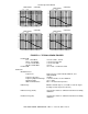
1.2 EQUIPMENT DESCRIPTION
The NAV 2000R VOR/ILS/COM Signal Generator contains necessary hardware and firmware to provide
modulated RF signals to verify operation of VOR navigational, ILS (Glideslope, Localizer, and Marker
Beacon), and COM communications LRU systems for aircraft. An external modulation signal can either
be summed with internal audio signals or separately controlled. The modulated RF output is connected
directly to the LRU. The NAV 2000R can be locally or remotely operated.
1.3 TECHNICAL CHARACTERISTICS
Mains Fuses
The equipment uses two type F, 1.6 A, 250 V, 5 mm X
20 mm fuses (A1F1 and A1F2).
To replace these fuses, which are located on the rear
panel inside the Appliance Inlet (A1FL1):
1. disconnect the appliance coupler.
2. With a flat blade screwdriver, or similar tool, open
the cover.
3. With a flat blade screwdriver, or similar tool, remove
the fuse holder/power input selection subassembly.
4. Replace fuse(s) with kind indicated above.
5. Replace the fuse holder/power input selection
subassembly so that voltage selected appears in
window when the cover is snapped into place.
Ac Power Source The equipment is intended to operate from an ac power
source that will not apply more than 253 V ac between
the supply conductors or between either supply
conductor and ground. A protective ground connection
by way of the grounding conductor in the power cord is
required for safe operation.
Environmental Specifications The environmental specifications are as follows.
Operating Temperature 5 °C to 40 °C.
Storage Temperature -20 °C to +85 °C.
Relative Humidity Maximum of 80% for temperatures up to 31 °C
decreasing linearly to 50% at 40 °C.
Operating Altitude 2 000 m maximum.
Size 14.5 cm H x 44.2 cm W x 49.0 cm D
(5.7” H x 17.4” W x 19.3” D)