
Technical data
Aeroflex Operation Manual
NAV 2000R SIGNAL GENERATOR - REV. 0 – JULY 26, 2007 - PG 1-3
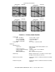
Mains Input Selection Selection of mains input range is done at the appliance inlet
(A1FL1) on the back panel. For 115 V ac ± 10%, set the
selector to the 115 V position. For 230 V ac ± 10%, set the
selector to the 230 V position. Either selection will accept 50
or 60 Hz.
To change the voltage selection:
1. Disconnect the appliance coupler.
2. With a flat blade screwdriver, or similar tool, open the
cover.
3. With a flat blade screwdriver, or similar tool, remove the
fuse holder/power input selection subassembly.
4. Rotate the assembly and push it back into position.
5. Check that the voltage selected appears in the voltage
selection window when the cover is snapped into place.
Max RF OUTPUT Safe Input Power
-50 (W/MOD STATUS 7) 50 W, 50 V dc
-TA 200 mW, 0 V dc
RF Frequency
Output Frequency Range 150 kHz to 450 MHz
Frequency Resolution 10 Hz
Frequency Drift ± 2.5 ppm
Reference Aging ± 1 ppm per year
Time Base
External Reference Input 10 MHz ±2.5 ppm (BNC/female connector on
backpanel) -2 dBm to +20 dBm 5 V dc max
Internal Reference Output 10 MHz, 0 dBm minimum.
RF Output level 0 dBm to -127 dBm
Accuracy
0 dBm to -64 dBm ± 1.0 dB
-64 dBm to -110 dBm ± 2.0 dB
-110 dBm to -127 dBm ± 3.0 dB
Level resolution 0.1 dB
Settling Time < 250 ms
SWR < 1.5:1
Output Impedance 50 Ω
Spectral purity
Harmonics < -30 dBc
Non-harmonics < -60 dBc at > 5 kHz from carrier
SSB Phase Noise < -115 dBc/Hz at > 25 kHz from carrier (CW only)