
Technical data
Aeroflex Operation Manual
NAV 2000R SIGNAL GENERATOR - REV. 0 – JULY 26, 2007 - PG 4-3
Both LOC and G/S consist of a 90 Hz tone and a 150 Hz tone at variable amplitudes depending upon the
DDM (Difference in Depth of Modulation) setting. The DSP processor computes the composite
modulating signal. First, it sets up the amplitude ratio needed to achieve the DDM setting based upon
which beam is selected as a reference: LEFT or RIGHT for localizer, TOP or BOTTOM for G/S. For LOC
only, an identification of either a 1020 Hz tone or a one to six letter Morse code word at 1020 Hz may be
added to the 90 Hz and 150 Hz tones. The audio signal for both LOC and G/S is applied to the audio
board attenuator where it is attenuated according to the current modulation percentage before amplitude
modulating the RF carrier on the RF modulator board. For G/S, the sum of the 90 Hz and 150 Hz
modulation percentages cannot exceed 99% and for LOC the sum of the 90 Hz, 150 Hz, and 1020 Hz
modulation percentages cannot exceed 99%.
Marker Beacon (MKR) audio signals are generated by the DSP processor board and are a user specified
tone. The MKR audio signal may be pulsed at a rate determined by the beacon selected: inner, middle,
or outer. The percent modulation is achieved by the attenuator on the audio board before amplitude
modulating the carrier on the RF Modulator Board. The marker beacon frequency may be programmed
away from its normal setting, anywhere from 10 to 18,000.0 Hz with 0.1 Hz resolution.
4.3.5 COM SIGNAL GENERATOR
The COM (Communications) audio signals are generated by the DSP board. One or two tones of user
specified frequency are generated by the DSP processor to test communications equipment. The
percent modulation is set by the system controller processor using the attenuator on the audio board.
The sum of the two tones is limited to 99%. Then, on the RF Modulator Board, the audio signal amplitude
modulates the RF carrier.
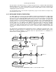
4.3.6 SYSTEM COMPUTER BOARD THEORY OF OPERATION
The system computer board controls the operation of the NAV 2000R. It consists of a microprocessor, a
boot ROM, four memories, a GPIB interface, a video generator, a keyboard interface, buss control
circuitry, discrete hardware control, and a slave controller. A block diagram of the board
(JPN 40-5742-00) is located in Section V of this manual.
The microprocessor starts by running EPROM boot code. This boot code, residing in EPROM, verifies
the operating code residing within the EEPROM. With operating code verified, program execution jumps
to the EEPROM.
The battery backed RAM contains system status flags, calibration information, global system parameters,
and the operator setup memory. Each mode may store up to 49 setups in program memory. When
saved, the complete system record is saved. Thus, when recalled, the system will return to that state.
Memory 0 recalls the factory set defaults.
The MUART (Multi-function Universal Asynchronous Receiver & Transmitter) provides serial
communication ability, discrete hardware control, additional timers, and a slave interrupt controller. The
slave interrupt controller has as inputs the key pressed interrupt, and the buss grant error interrupt.
These in turn are hardware interrupts to the processor.
The GPIB interface provides a GPIB talker/listener ability. Provision for a GPIB controller is also present
but is not implemented.
The video generator decodes row and column data and transmits the data to the display. Also, the
microprocessor generates the horizontal and vertical sync signals. A 16.384 MHz clock is provided to the
display to clock in data.