
Technical data

Aeroflex Operation Manual
NAV 2000R SIGNAL GENERATOR - REV. 0 – JULY 26, 2007 - PG 4-5
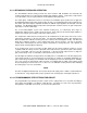
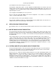
FIGURE 4-1: VOR SIGNAL GENERATOR BLOCK DIAGRAM
The following equation describes the VOR mode:
A
c
SIN(w
c
t
i
- (df/f
m
).COS(w
m
t
i
))
+ A
v
SIN(w
v
t
i
) + A
i
SIN(w
i
t
i
)
where,
A
c
= Amplitude of the carrier signal.
A
v
= Amplitude of the reference signal.
A
i
= Amplitude of the ident signal.
w
c
t
i
= Instantaneous phase of the carrier.
w
m
t
i
= Instantaneous phase of the modulation signal.
w
v
t
i
= Instantaneous phase of the reference.
w
i
t
i
= Instantaneous phase of the ident tone.
df = Peak frequency deviation = +/- 480 Hz
f
m
= Frequency modulation = 30 Hz