Aerohive AP330 and AP350 User Guide
Aerohive AP330 and AP350 User Guide Aerohive Technical Publications To register, get the latest product documentation, see compliance information, and download software updates, visit www.aerohive.com/support. Copyright Notice Copyright © 2012 Aerohive Networks, Inc. All rights reserved. Aerohive Networks, the Aerohive Networks logo, HiveOS, HiveAP, and HiveManager are trademarks of Aerohive Networks, Inc. All other trademarks and registered trademarks are the property of their respective companies.
About This Guide This guide describes Aerohive AP330 and AP350 devices, including component descriptions, installation and mounting instructions, wiring diagrams, and hardware specifications.
Contents Aerohive AP330 and AP350 ..................................................................................................... 7 AP330 and AP350 Product Overview ..................................................................................... 8 Ethernet and Console Ports............................................................................................. 10 Aggregate and Redundant Interfaces .................................................................. 11 Console Port ............
Contents 6 Aerohive
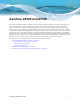
Aerohive AP330 and AP350 The AP330 and AP350 are 802.11n wireless access points designed for greater throughput and range, with the added capability of being configured as routers. They provide dual concurrent 802.11b/g/n and 802.11a/n radios for 3x3 MIMO (Multiple Input Multiple Output) antenna configurations and three spatial streams. When you enable 802.
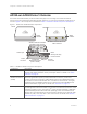
Chapter 1 Aerohive AP330 and AP350 AP330 AND AP350 PRODUCT OVERVIEW The AP330 and AP350 models provide excellent throughput and coverage. The AP330 has internal antennas, and the AP350 has detachable external antennas. You can see the hardware components on the AP in Figure 1. Each component is described in Table 1 "AP330 and AP350 component descriptions".
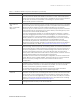
AP330 AND AP350 PRODUCT OVERVIEW Table 1 AP330 and AP350 component descriptions (Continued) Component Description Power Connector The 12-volt DC power connector (2.0 amps) is one of two methods through which you can power the AP330 and AP350. To connect it to a 100 – 240-volt AC power source, use the AC/DC power adaptor that is available as an extra option. Because the AP does not have an on/off switch, connecting it to a power source automatically powers on the device.
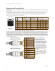
Chapter 1 Aerohive AP330 and AP350 Ethernet and Console Ports There are three ports on the AP330 and AP350: two RJ-45 10/100/1000Base-T/TX Ethernet ports and an RJ-45 console port. The pin assignments in the Ethernet ports follow the TIA/EIA-568-B standard (see Figure 2). The ports accept standard types of Ethernet cable—cat3, cat5, cat5e, or cat6. Because the ports have autosensing capabilities, the wiring termination in the Ethernet cable can be either straight-through or cross-over.
AP330 AND AP350 PRODUCT OVERVIEW The ETH0 port can receive PoE through an Ethernet cable connected to PSE that is 802.3af- or 802.3at-compatible. Such equipment can be embedded in a switch or router, or it can come from purpose-built devices that inject power into the Ethernet line en route to the AP. Aerohive provides several PoE injectors as accessories that you can order: AH-ACC-INJ-30W-EU, AH-ACC-INJ-30W-UK, AH-ACC-INJ-30W-US, AH-ACC-INJ-30W-AU, and AH-ACC-INJ-30W-IL.
Chapter 1 Aerohive AP330 and AP350 Switch(config-if)#exit Switch(config)#int fastEthernet 0/2 Switch(config-if)#switchport mode access Switch(config-if)#channel-group 1 mode on Switch(config-if)#spanning-tree portfast Switch(config-if)#exit Switch(config)#exit Switch#wr mem Finally, you must cable the Cisco switch and the AP together: Cisco 0/1 to AP eth0, and Cisco 0/2 to AP eth1.
AP330 AND AP350 PRODUCT OVERVIEW Console Port The pin-to-signal mapping in the RJ-45 console port is shown in Table 2 "Console port pin assignments".
Chapter 1 Aerohive AP330 and AP350 USB Modem Port When configured as routers, AP330 and AP350 devices can use a wireless USB modem for a WAN connection. The typical use of the USB modem is to act as a backup to the ETH0/WAN interface; however, for locations where an Ethernet connection to the WAN is not possible, you can use the USB modem as the primary (and only) interface to the WAN.
AP330 AND AP350 PRODUCT OVERVIEW directions in a toroidal (donut-shaped) pattern. For greater coverage on a horizontal plane, it is best to orient the antennas vertically. So that you can easily do this whether the AP is mounted horizontally or vertically, the articulated antennas hinge and swivel. The non-articulated antennas are intended for wall installations and have a fixed orientation in the same direction as the antenna connectors.
Chapter 1 Aerohive AP330 and AP350 Figure 6 Directional antenna patterns (Bird’s eye view) Patch antennas Lower gain Higher gain Omnidirectional Antennas You typically orient omnidirectional antennas vertically, positioning them on all devices in the same direction. Omnidirectional antennas create coverage areas that can be toroidal (doughnut-shaped) or cardioid (heart- or plum-shaped), broadcasting to the sides much more effectively than up or down (see Figure 7).
MOUNTING THE AP330 OR AP350 MOUNTING THE AP330 OR AP350 Using the mounting plate and track clip, you can mount the AP330 or AP350 to the tracks of a dropped ceiling grid. Using just the mounting plate, you can mount the AP to any surface that can support its weight (AP330: 1.5 lb., 0.68 kg; AP330: 2.375 lb. (1.08 kg)).
Chapter 1 Aerohive AP330 and AP350 Figure 9 Attaching the AP to the rail mount 3 With the AP upside down, align the two V-shaped tabs and the security tab extension on the rail mount with the tab slots and security screw cavity on the AP, and press the AP upward until it snaps into place.
MOUNTING THE AP330 OR AP350 Locking the AP330 and AP350 To lock the AP to the rail mount or mounting plate, use either a Kensington lock or the security screw that is included with the mounting kit. To use a Kensington lock, loop the cable attached to the lock around a secure object, insert the T-bar component of the lock into the device lock slot on the AP, and then turn the key to engage the lock mechanism.
Chapter 1 Aerohive AP330 and AP350 CONNECTING THE AP TO THE NETWORK Run an Ethernet cable from the eth0 port on the AP to a switch so that on the network. You can use an AC/DC power adaptor to connect it to a 100-240 VAC power source or allow it to obtain power through PoE (Power over Ethernet) from PSE (power sourcing equipment) on the network. (Power adaptors and PoE injectors are available from Aerohive as options.
DEVICE, POWER, AND ENVIRONMENTAL SPECIFICATIONS DEVICE, POWER, AND ENVIRONMENTAL SPECIFICATIONS Understanding the range of specifications for the AP330 and AP350 is necessary for optimal deployment and device operation. The following specifications describe the physical features and hardware components, the power adapter and PoE (Power over Ethernet) electrical requirements, and the temperature and humidity ranges in which the devices can operate.
Chapter 1 Aerohive AP330 and AP350 22 Aerohive
Index Index A aggregate interface 11 antennas articulated and non-articulated, AP350 14 configuring 15 connectors, AP350 8 directional 16 internal, AP330 14 omnidirectional 16 patch 15 single-direction 15 AP330 7–21 antennas 14 antennas, internal 14 console 8, 11, 13, 21 environmental specifications 21 Ethernet port 9, 21 Ethernet ports 10, 11 gain 14 impedance 14 LED brightness control 14 locking 9, 19 mounting, ceiling 17 mounting, surface 18 PoE 9, 11, 20 power connector 9 power specifications 21 reset
Index 24 Aerohive
Aerohive HiveAP Compliance Information Federal Communication Commission Interference Statement Only attach antennas that are certified for use with this device. Replacing antennas with unauthorized, high-gain antennas greatly increases the risk of interference and invalidates the FCC certification.