AeroScout Location Receiver User Guide 1450 Fashion Island Blvd. Suite 510 San Mateo, CA 94404 Tel: 650-571-0800 Fax: 650-571-6660 www.aeroscout.
Disclaimer The information and know-how included in this document are the exclusive property of AeroScout Inc. and are intended for the use of the addressee or the user alone.
Introduction | 3 Table of Contents Introduction........................................................................................................ 5 Location Receiver Hardware............................................................................. 5 Antennas ........................................................................................................... 8 Location Receiver Installation .........................................................................
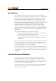
Introduction | 5 Introduction The AeroScout Location Receiver is a component of the AeroScout Wireless LAN Location Platform. AeroScout’s expertise in wireless signal measurement has lead to the development of a range of patent-pending algorithms and techniques embedded in the Location Receiver. These measure the time of arrival (TOA) of standard 802.11b messages to the nanosecond.
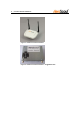
| Location Receiver Hardware Figure 1. AeroScout Location Receiver Figure 2.
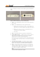
Location Receiver Hardware | 7 Figure 1 describes the AeroScout Location Receiver panels and indication LEDs. 1 2 3 4 5 6 4 Figure 1. AeroScout Location Receiver front and back panels 1 Power – Green LED indicates that the unit is ON and connected to a power source. 2 Status – Green LED indicates the unit’s operational status. a. Blinking fast (several times per second) – Location Receiver is associated to the AeroScout Engine and sending location data to it. b.
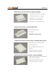
| Antennas Antennas This section shows the supported antennas by the AeroScout Location Receivers. Note Antennas are selected according to specific site and system requirements. Before changing antennas, please consult with your vendor. 5.5dBi Omni-directional Antenna - Max Rad MMO24005PT • Vertical polarization • Horizontal beam width – 360 degrees • Vertical beam width – 32 degrees • Length – 11.
Antennas | 9 8dBi Directional Flat Patch Antenna - High Gain HG2409P • Horizontal beam width – 75 degrees • Vertical beam width – 65 degrees • Dimensions – 4.5” X 4.5” X .9” (114mm X 114mm X 23mm) • Horizontal or vertical polarization 5dBi Directional Antenna - Cushcraft SR2405135D • Wide H-plane antenna • 135 degrees • Dimensions - 3" X 6" X 2" (76mm X 152mm X 51mm) 6.
| Location Receiver Installation 2 dBi Omni-directional Dipole Rubber Antenna - Hankook TB2400S • Vertical polarization • Antenna length: 6.7” (170mm) Note Indoor cables for antennas are of type RF Coaxial Cable RG316 SMA(RP)-NT. These are available in the following lengths: ½ m, 1m, 2m, and 3m. Location Receiver Installation Connecting to the Power Source The Location Receivers can be powered externally or over the Ethernet network using a standard 802.3af power injector.
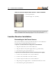
Location Receiver Installation | 11 Mounting the Location Receiver The Location Receiver shall be mounted vertically with the LEDs panel pointing to the bottom. The unit (and antennas) shall be stable during normal operation. The unit should be installed in a ventilated area not exposed to direct sun. Do not to install the unit near heat sources and/or other RF antennas. The Location Receiver should be firmly mounted on a fixed surface using two screws.
| Location Receiver and Accessories Model Numbers Location Receiver and Accessories Model Numbers AeroScout Location Receiver AeroScout Location Receiver Comments Model Number Includes 2 Omni-directional dipole rubber antennas, 802.3af Power over Ethernet and power adapter. BWH1000-02 AeroScout Location Receiver – Ruggedized Unit Location Receiver unit in a metal housing. BWH1000-02-R AeroScout Tag Activator Includes 2 Omni-directional dipole rubber antennas, Low Frequency antenna, 802.
Location Receiver Specifications | 13 Location Receiver Specifications Performance • Outdoor range: up to 200m (600 feet) • Indoor range: up to 60m (180 feet) • Over 300 measurements processed per second (system capacity depends on the server’s processing power as well) • Patent-pending signal-processing algorithms • Supports standard Wi-Fi (802.11b) clients and AeroScout tags Physical and Environmental Specifications • Dimensions: 5.51” x 4.33” x .1.
| Location Receiver Specifications Certifications • Radio: FCC Part 15, sub-part C class B, sub-part B EN 300-328, EN 301-489, EN 300-330 RSS 210 (Canada) ARIB STD-T66 (Japan), ARIB STD-33 (Japan) • Safety: CE, cTUVus (EN60950)
| 15 Safety and Warnings FCC STATEMENT This equipment has been tested and found to comply with the limits for a Class B digital device, pursuant to Part 15 of the FCC rules. These limits are designed to provide reasonable protection against harmful interference in a residential installation. This equipment generates, uses and can radiate radio frequency energy and, if not installed and used in accordance with the instructions, may cause harmful interference to radio communications.
| DISCLAIMER OF WARRANTY. EXCEPT AS SPECIFIED IN THIS WARRANTY, ALL EXPRESS OR IMPLIED CONDITIONS, REPRESENTATIONS, AND WARRANTIES INCLUDING, WITHOUT LIMITATION, ANY IMPLIED WARRANTY OR CONDITION OF MERCHANTABILITY, FITNESS FOR A PARTICULAR PURPOSE, NONINFRINGEMENT, SATISFACTORY QUALITY OR ARISING FROM A COURSE OF DEALING, LAW, USAGE, OR TRADE PRACTICE, ARE HEREBY EXCLUDED TO THE EXTENT ALLOWED BY APPLICABLE LAW.