
User's Manual


Location Receiver Hardware | 7
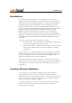
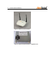
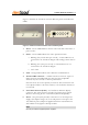
Figure 1 describes the AeroScout Location Receiver panels and indication
LEDs.
3
1
2
5
4
4
6
Figure 1. AeroScout Location Receiver front and back panels
1 Power – Green LED indicates that the unit is ON and connected to a
power source.
2 Status – Green LED indicates the unit’s operational status.
a. Blinking fast (several times per second) – Location Receiver is
associated to the AeroScout Engine and sending location data to
it.
b. Blinking slow (once per second) - Location Receiver is not
associated to the AeroScout Engine.
c. Off - Fault
3 Link – Orange LED indicates active Ethernet communication.
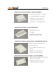
4 Antenna SMA connector – 2.4GHz antenna connectors. A pair of
dipole antennas is included with the unit, but other compatible
antennas may also be used to enhance performance.
Note that those are reverse polarity connectors. The left antenna next
to the RJ-45 interface is the main antenna, to be used when diversity is
not selected.
5 Local Area Network (LAN) – 10/100 base-T Ethernet (RJ-45)
connector. The same connector is used for powering the Location
Receiver when using Power over Ethernet (802.3af compatible).
6 Power – The power jack provides connection to an external power
supply. The adapter rating is 5V/1.5A and positive center pole. The
110/220VAC power adapter is supplied with the Location Receiver
and available in US/Japan or Europe models.
Note
Use only AeroScout-supplied power supplies.