
User's Manual


AeroScout EX5100 Exciter
EX5100 Hardware 9
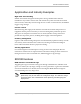
1. Ethernet LAN Connection – RJ-45 interface. In a configuration that uses a physical
Ethernet cable connection to the LAN, the network cable is attached here. Permanent
connection to a wired network is not mandatory. However you must have a wired
connection for configuring the Exciter. In addition, some of the monitoring functions
will not be available if the Exciter is not wired. This connection is also used for
Power over Ethernet (PoE, 802.3af).
2. Power jack – Accepts an input voltage of 48V DC. This is a standard 2.5mm jack
connector for direct power supply. Alternatively, you can use the power supply that
is packaged along with the Exciter. When PoE is used, this connection is not used.
3. Chain IN Connector – RJ-45 connector. This connector is used for receiving power
from chained Exciters.
4. Chain OUT and Control Connector – RJ-45 connector. This connector is used for
distributing power to chained Exciters. The output voltage is 12V DC (0.5A
maximum).
5. Auxiliary connector – Designed for connecting an External Speaker unit.
WARNING: The auxiliary connection is for connecting an External Speaker
unit only. Connecting other devices or a POE connection to the auxiliary
input may harm the Exciter.
6. Termination Switch – For defining termination settings in a chained Exciters
installation. The default factory setting is Termination On (o-o). In chained Exciters
installations, the termination of the first and last Exciters in the chain should be set to
On (o-o) and the rest should be set to Off (-o-o-).
7. IP Reset Switch: Restores the device’s IP address to the company default.