
Installation and Operation Manual


4.9.13 © Inovonics, 2013 - www.inovonics.com 2
4 One-Way Serial RF Module Connections and
Output Jumpers
5 Installation
A The RF module must only be connected at the eight pin header or eight pin plated
thru-holes.
B All cables and wires must be routed away from the component side of the RF
module.
C The integrated antenna must not be tampered with; no connection to an alternate
antenna is provided.
D The application module must not include an integrated secondary colocated radio
module.
E The one-way serial data RF module antenna should be placed so that it is facing
away, or otherwise isolated from, your device’s ground plane.
F Components that are sensitive to RF transmission, such as high gain circuits,
should be isolated from the antenna to prevent interference.
G One-way serial RF modules should not be mounted on metal surfaces or inside
metal enclosures. They should also not be mounted where sheet metal ductwork,
wire mesh screens, etc. might block transmissions.
H The RF module should be integrated so the antenna is unobstructed by the end
user’s PCB, batteries, or any other conductive material.
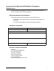
Figure 5 The RF module should be integrated so the antenna is unobstructed
6 One-Way Serial RF Module Requirements
6.1 Timing requirements
All data is sent at a default rate of 9600 baud, no parity, 8 data bits and one stop bit.
The data is transmitted least significant bit first.
6.2 Power Requirements
The E*1941XS has an on-board voltage regulator. Connect power cabling to an
external power supply (Vcc) of 2.4 to 5.5 volts. Voltage must be sustained at 2.4 volts
or above and supply 100 milliamps during the transmit cycle.
EN1941XS
Assuming check-in messages every 3 minutes and infrequent alarm messages (one
per day, on average), the average current draw is 32 uA. Peak current draw while
transmitting is less than 100 mA. One alarm/restore cycle with the maximum payload
size results in approximately a 23mA increase in the average current.
EE1941XS
Assuming check-in messages every 12 minutes and infrequent alarm messages (one
per day, on average), the average current draw is 15 uA. Peak current draw while
transmitting is less than 50 mA. One alarm/restore cycle with the maximum payload
size results in approximately a 12mA increase in the average current.
6.3 Low Battery Condition
The E*1941XS measures power supply voltage every three and a half hours, and,
when the voltage measures 2.4 volts, a serial message is sent indicating a low battery
condition.
6.4 Temperature range
-20°C to +60°C, non-condensing
6.5 RF network compatibility
EchoStream Commercial Mesh Network
6.6 Payload size
50 bytes maximum
6.7 Input Requirements
Caution: Input levels must not exceed 3.3 V.
Open When an active source (open collector or dry contact) is used to drive the alarm
or tamper input, the voltage should be between 0.75xVcc and Vcc. A passive input
should have an impedance of greater than 5.1k ohm between the input and ground.
Closed When an active source is used, the voltage should be less than 0.25xVcc. A
passive input should have an impedance of less than 240 ohm.
6.8 Serial I/O - UART logic-levels
Input levels must not exceed 3.3 V. Output levels are limited to 3.3 V, maximum.
Data in pins Vih (minimum high level input voltage): 0.75xVcc
Data in pins Vil (maximum low level input voltage): 0.25xVcc
Data out pins Voh (minimum high level output voltage): Vcc - 0.25 at Ioh: -1.5mA
Data out pins Voh (minimum high level output voltage): Vcc - 0.6 V at Ioh: -6mA
Data out pins Vol (maximum low level output voltage): 0.25 V at Iol: 1.5mA
Data out pins Vol (maximum low level output voltage): 0.6 V at Iol: 6 mA
7 Compliance Requirements
7.1 FCC Requirements for the EN1941XS
The EN1941XS one-way serial data RF module has received a Limited Modular
Grant, requiring Inovonics to retain control of the final installation to ensure
compliance to FCC/IC regulations. The integrator is responsible to test the final
installation to verify compliance to FCC/IC regulation for unintentional emissions.
Prior to marketing the product, the integrator must complete and submit to Inovonics a
compliance review form and documentation, and, if requested, a functional product
sample for approval. If this is not possible, the integrator must perform the testing
themselves and submit proof to Inovonics of compliance to Part 15 of the FCC Rules
and Industry Canada RSS-210.
At the end of this guide is an Inovonics compliance review form to be filled out by the
integrator.
The integrator is also responsible for properly labeling the product containing the one-
way serial data RF module. Labels must be placed on the outside of the product, and
must include a statement indicating that the product contains the module, along with
the FCC and IC number.
Example 1 “Contains One-Way Serial RF Module
FCC ID: HCQ3B6OT9OEM; IC ID: 2309A-OT9OEM (EN1941XS-IC)”
Example 2 “Contains FCC ID: HCQ3B6OT9OEM; IC ID: 2309A-OT9OEM
(EN1941XS-IC)”
7.2 Television and Radio Interference
This equipment has been tested and found to comply with the limits for a Class B
digital device, pursuant to Part 15 of the FCC Rules. These limits are designed to
provide reasonable protection against harmful interference in a residential installation.
This equipment generates, uses and can radiate radio frequency energy and, if not
installed and used in accordance with the instructions, may cause harmful
interference to radio communications. However, there is no guarantee that
interference will not occur in a particular installation. If this equipment does cause
harmful interference to radio or television reception, which can be determined by
turning the equipment off and on, the user is encouraged to try to correct the
interference by one or more of the following measures:
• Reorient or relocate the receiving antenna.
• Increase the separation between the equipment and receiver.
• Connect the equipment into an outlet on a circuit different from that to which the
receiver is connected.
• Consult the dealer or an experienced radio/TV technician for help.
8 FCC Part 15 and Industry Canada Compliance
This device complies with part 15 of the FCC Rules and Industry Canada license-
exempt RSS standard(s). Operation is subject to the following two conditions: (1) this
device may not cause interference, and (2) this device must accept any interference,
including interference that may cause undesired operation of the device.
Le présent appareil est conforme aux CNR d'Industrie Canada applicables aux
appareils radio exempts de licence. L'exploitation est autorisée aux deux conditions
suivantes : (1) l'appareil ne doit pas produire de brouillage, et (2) l'utilisateur de
Connection Output Jumper N/C
Primary Alarm
Open Alarm
Ground Alarm Clear
Secondary
Alarm
Open Alarm
Ground Alarm Clear
Tamper
Open Tamper
Ground Tamper Clear
Reset
Open for normal operation; connect to the ground and
release for a board reset.
End user
application
printed circuit
board
RF
module
Clear transmit
region in front
and back of
antenna