
Manual

General Installation, Operation and Maintenance Instructions For Aerovent Products
©2014 Aerovent
1.0 GENERAL DESCRIPTION
Model ATA and ATABD axial fans come in various configura-
tions that offer flexibility to meet the needs of the end user.
1.2 DEFINITIONS
An axial fan consists of a propeller type impeller,
motor driven and ducted or shrouded so that the blades are
enclosed to increase operating efficiency.
An adjustable pitch impeller is one where the blade
angle can be changed, but only when the propeller is stationary.
1.3 Arrangements
Fans are available in two different configurations,
defined as follows:
Arrangement 4 (ATA) — The impeller is mounted
directly on the motor shaft with both motor and impeller
enclosed in the fan case.
Arrangement 9 (ATABD) — The impeller is mounted
on a bearing-supported shaft, belt driven by a motor sup-
ported on the fan case.
1.4 APPLICATION
Fans can be installed in a free inlet or ducted inlet appli-
cation. Mounting arrangements include legs for floor mount-
ing, flanges for direct duct connections or brackets for vertical
or horizontal mount from the floor or ceiling.
1.5 ACCESSORIES
The following accessories are available on Model ATA
and ATABD fans.
a. Inlet bell
b. Inlet screen
c. Inlet and outlet cones
d. Companion flanges
e. Flexible connectors
f. Vibration isolators
g. Radial inlet vane dampers
h. Backdraft dampers
1.6 OPTIONS
a. Legs for horizontal floor mounting
b. Clips for horizontal ceiling suspension
c. Brackets for vertical floor or suspension mounting
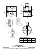
1.6 NAMEPLATE NOMENCLATURE
The model number information on each fan nameplate is
explained in Figure 1.
2.0 INSTALLATION
2.1 RECEIVING/INSPECTION/STORAGE
All fans are shipped on wooden pallets. Each fan is
normally covered with plastic for weather protection. The fan
should remain on the pallet and covered or protected from the
weather until installation.
Carefully inspect the fan upon arrival for damage
incurred during shipment. Immediately report any damage to
both the factory and the carrier. For short-term storage, prior
to installation, the fan should remain covered with plastic
wrap on the shipping pallet and stored in a clean, dry location
away from the elements. If storage is to be for a period longer
than six (6) months, consult factory for long-term storage
instructions.
2.2 LIFTING
Fans should be lifted using slings. The slings can be
placed under the pallet and a spreader bar used as required.
2.3 MOUNTING
Depending on the type of fan support specified, the
fan can be floor mounted on legs, supported on a structural
frame for vertical airflow or ceiling hung by clip supports or
duct mounted.
Figure 1.
MODEL ATA & ATABD TUBEAXIAL FANS
100 - A - 3 - 27 - ATABD - 1067 - 10
Wheel Dia. (cm)
035, 040, 050
063, 071, 080
090, 100, 112
125
Propeller Design
No. of Blades
3 or 6
Blade Angle (Degrees)
Fan Type
ATA = Direct Drive
ATABD = Belt Drive
Fan RPM
Motor HP
IM-401
August 2014
®