
Manual

2 Aerovent IM-401
2.3.1 Vibration Isolators
All fans are dynamically balanced to reduce vibration.
However, it is recommended that the fan be supported on
vibration isolators. Isolators should be selected for each instal-
lation in accordance with individual requirements. Concrete
inertia pads are generally not required with ATA and ATABD
fans.
2.4 DUCT CONNECTIONS
All fans should be aligned with the ductwork. A flexible
connection should be provided between the fan and duct to
prevent structure-borne noise from being transmitted to the
ductwork.
If the fan is to be attached directly to the duct without
a flexible connection, special care must be exercised to align
the fan and duct flanges so the fan is not subject to structural
loads from the ductwork. These loads could distort the fan
housing, causing the blades to hit or rub the case, or change
the blade tip to housing clearance and affect performance.
2.5 ELECTRICAL
All wiring should conform to local electrical codes and
the job specification. In NEMA standard MG-2, the phenom-
ena of transient torques is addressed. We advise that measures
be taken to protect your equipment from transient torque and
power interruptions.
2.5.1 Power Connection
The motor leads terminate in the conduit box. The
leads are factory connected for the voltage specified for the
job. Motor leads for wye-delta and part-winding starts are
not connected. Rigid conduit should be run from the motor
starter to the fan with a short section of flexible conduit at the
conduit box to allow for fan movement.
Wire size and motor overloads should be sized in
accordance with the fan nameplate electrical data. The conduit
box is located on the outside of the case on all direct driven
fans. On belt driven fans the motor is outside the fan case and
the connection will be made directly to the motor.
2.5.2 Motor Rotation
Check motor rotation by jogging the motor. The pro-
peller should rotate in the direction indicated by the rotation
arrow on the fan case. It is important that correct motor rota-
tion be established on ducted fans as the propeller will not be
visible after an inlet duct is installed. Reverse any two motor
leads to change direction of rotation of three-phase motors.
2.5.3 Final Check Before Putting
Fan Into Operation
1. Check for correct supply voltage and motor overloads.
2. Insure that all loose debris is removed from fan and ducts.
3. Check that the propeller is centered in the fan case and that
the blade tip clearance is not less than the minimum values
in Figure 2.
4. Hand rotate to assure free movement.
5. Bump the fan starter to check rotation.
6. Start the fan and verify that the vibration levels are
satisfactory.
7. Check the current draw. Do not exceed the full load amper-
age as specified on the nameplate.
3.0 FAN BLADE ADJUSTMENT
3.1 GENERAL
Models ATA and ATABD feature an adjustable pitch
propeller. The blade pitch has been factory set to meet the
airflow requirement of the job specification. If required, the
pitch may be changed to meet other airflow requirements on
the job site. Contact the factory for recommended new setting
and request an AXIPAL blade protractor.
NOTE: If the blade angle is reduced by more than five
(5) degrees from the value preset on delivery, the clearance
between the blades and the casing will be reduced. Check that
the blade tip clearance is not less than the minimum values in
Figure 2. If the blade angle is increased, check the tip clear-
ance for minimum clearance as the leading and trailing tips will
get closer to the fan casing.
4.0 MAINTENANCE
4.1 GENERAL
ATA and ATABD fans are a quality product designed
and manufactured for minimum maintenance and long operat-
ing life. They should provide years of trouble-free service if
the following maintenance procedures are followed.
There are no moving parts in the propeller assembly.
Therefore, routine maintenance is generally limited to motor
lubrication, bearing lubrication of the belt driven models and
belt replacement.
4.2 FAN BALANCE
The propeller assembly shall be statically and dynami-
cally balanced in accordance with ANSI/AMCA 204-96
"Balance Quality and Vibration Levels for Fans" to Fan
Application Category BV - 3, Balance Quality Grade G6.3. In
addition, direct drive fan propellers shall be balanced on the
motor shaft after final assembly in the fan casing, in the manu-
facturing facility, to the following peak velocity values, filter-in,
to the fan test speed:
Fan Application Rigidly Mounted Flexibly Mounted
Category (in./s) (in./s)
BV-3 0.15 0.20
4.3 LUBRICATION
4.3.1 Motor Lubrication
Motor bearings do not require initial lubrication unless
the fan has been in storage over six months. If this is the case,
the motor should be lubricated initially.
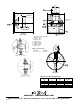
Figure 2.
NOMINAL BLADE TIP CLEARANCE (INCHES)
FAN SIZE MINIMUM NOMINAL MAXIMUM
035 .028 .063 .098
040 .032 .071 .110
050 .039 .087 .134
063 .047 .110 .173
071 .055 .126 .197
080 .063 .142 .220
090 .079 .177 .276
100 .079 .177 .276
112 .098 .217 .335
125 .098 .217 .335