
Service Manual


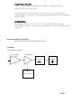


Charge Pump and Loop Filter
The IC1 pin5 and associated resistors make VCO loopFilter . The charge pump output
Produce a 0 to 5V tuning voltage signal.
The signal is filtered by the loop filter (R14,C15 and C20) to remove any residual reference
Frequency harmonics from the signal.. After filtering the signal is applied to the voltage controlled
Oscillator module.
DC REGULATOR
The DC Regulator IC2, converts the +13.6 V to a 8V supply . This is used to provide the
Tuning voltage for the VCO . A wide voltage range is required to allow for the wideband operation
Of the radio .
Dual modulus prescaler
The prescaler divides the VCO frequency by 64 or 65.
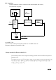
Transmitter
The transmitter comprises:
VCO Buffer PA Module
Amp
PAGE7
RF LPF
ANTENNA
SWITCH
Automatic
Power Control