
User's Manual


Configuration interface
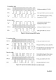
The microcontroller interface is shown in figure 5. The microcontroller uses 3 or 4 I/O pins for the
configuration interface(PDI, PDO, PCLK and PSEL). PDO should be connected to an input at the
microcontroller. PDI, PCLK and PSEL muse be microcontroller outputs. One I/O pin can be saved if PDI
and PDO are connected together and a bi-directional pin is used at the microcontroller.
The microcontroller pins connected to PDI, PDO and PCLK can be used for other purposes when the
configuration interface is not used. P
DI, PDO and PCLK are high impedance inputs as long as PSEL is not
activated (active low).
PSEL has an internal pull-up resistor and should be left open (tri-stated by the microcontroller) or set to a
high level during power down mode in order to prevent a trickle current flowing in the pull-up.
Signal interface
A bi-directional pin is used for data (DIO) to be transmitted and data received. DCLK providing the data
timing should be connected to a microcontroller input.
As an optional, the data output in receive mode can be made available on a separate pin.
PLL lock signal
Optionally, one microcontroller pin can be used to monitor the lock signal. This signal is at low logic level
when the PLL is in lock. It can also be used for carrier sense and to monitor other internal test signals.
PAGE7