
User's Manual


Transmitter
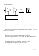
The transmitter comprises:
PA Buffer PA Module
Amp
Buffer
When the radio is in transmit mode the U1 is generated RF signal pass to the buffer/pre-amplifier Q1
and Q2 associated components.
PA module
The Q2 output signal is passed to Q3 via a matching network consisting of Inductor L5 , L15 and C32
and C34. Q3 is power amplifier .
Low pass filter
The amplified RF signal is passed through the stripline coupler and is fed to the
harmonic low pass filter, comprising L11, L12, L17 and C46 , C47, C48 and C58 and then to the
antenna connector (J1).
Antenna Switch
When transmitting, the diodes D3 are forward biased, the RF pass to the antenna.
D4 is shorted to ground which makes L13 look open circuit (1/4 wave
tuned stub). This prevents the TX signal from passing to the receiver stage.
PAGE6
RF LPF
ANTENNA
SWITCH
Power Control