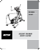
FOR MODEL: 18.0 AXT ASCENT TRAINER USER’S GUIDE 18.0 AXT Rev.2.4.
INTRODUCTION INTRODUCTION IMPORTANT PRECAUTIONS CONGRATULATIONS and THANK YOU for your purchase of this AFG Ascent Trainer! ASSEMBLY Whether your goal is to win races or simply enjoy a fuller, healthier lifestyle, an AFG Ascent Trainer can help you attain it – adding club-quality performance to your at-home workouts, with the ergonomics and innovative features you need to get stronger and healthier, faster.
INTRODUCTION IMPORTANT PRECAUTIONS Read all instructions before using this ascent trainer. When using an electrical product, basic precautions should always be followed, including the following: Read all instructions before using this ascent trainer. It is the responsibility of the owner to ensure that all users of this ascent trainer are adequately informed of all warnings and precautions.
ASSEMBLY STEP 1 DIAGRAM AND PARTS LIST WASHER (B) 34 mm Qty: 8 INTRODUCTION INTRODUCTION BOLT (A) 20 mm Qty: 8 HARDWARE BAG 1 CONTENTS: HEART RATE HAND GRIPS WASHER (B) 20 mm Qty: 8 IMPORTANT PRECAUTIONS IMPORTANT PRECAUTIONS BOLT (A) 20 mm Qty: 8 CONSOLE ASSEMBLY STEP 1: UPPER HANDLEBAR WATER BOTTLE HOLDER CONSOLE MAST TOP HAND RAIL LOWER HANDLEBAR SWING ARM BRACKET MAIN FRAME MAIN FRAME SIDE COVER SWING ARM CAP FRONT STABILIZER TUBE FRONT STABILIZER TUBE PEDAL ARM ELBOW COVER MAIN FRA
Side View BOLT (F) 25 mm Qty: 4 NUT (G) 8 mm Qty: 4 ASSEMBLY STEP 3 HARDWARE BAG 3 CONTENTS: WASHER (D) 25 mm Qty: 4 BOLT (C) 16 mm Qty: 12 IMPORTANT PRECAUTIONS NUT (G) 8 mm Qty: 4 ARC WASHER (E) 17 mm Qty: 8 Side View AXLE Qty: 2 ASSEMBLY STEP 2: IMPORTANT PRECAUTIONS HARDWARE BAG 2 CONTENTS: BOLT (F) 25 mm Qty: 4 ASSEMBLY STEP 3: BOLTS (F) INCLINE ARM TOP HANDRAIL ASSEMBLY TOP HANDRAIL ASSEMBLY INTRODUCTION A S S E M B LY S T E P 2 ARC WASHER (E) 17 mm Qty: 8 INTRODUCTION WASHER
ASSEMBLY STEP 5 HARDWARE BAG 4 CONTENTS: BOLT (N) 12 mm Qty: 6 BOLT (C) 16 mm Qty: 4 WASHER (L) 18 mm Qty: 4 WASHER (O) 34 mm Qty: 4 HARDWARE BAG 5 CONTENTS: LEFT UPPER BOLT (H) BOLT (C) HANDLEBAR SHAFT HANDLEBAR 20 mm 16 mm WAVY WASHER (J) Qty: 8 Qty: 2 REAR MAST COVER BOLTS (H) ASSEMBLY STEP 4: WASHER (I) 34 mm Qty: 2 WAVY WASHER (J) 23 mm Qty: 2 RIGHT UPPER HANDLEBAR ASSEMBLY STEP 5: WASHER (I) BOLT (C) BOLT (C) WASHER (I) ASSEMBLY LEFT UPPER HANDLEBAR CONSOLE HANDLEBAR SHAFT WAVY WASHER (
BOLT (C) 16 mm Qty: 2 ASSEMBLY STEP 7 HARDWARE BAG 6 CONTENTS: WASHER (D) 17 mm Qty: 2 WASHER (P) 38 mm Qty: 2 WAVY WASHER (M) 34 mm Qty: 2 HARDWARE BAG 7 CONTENTS: WASHER (L) 18 mm Qty: 8 BOLT (K) 12 mm Qty: 8 IMPORTANT PRECAUTIONS WASHER (D) 38 mm Qty: 2 INTRODUCTION A S S E M B LY S T E P 6 WASHER (I) 18 mm Qty: 8 BOLT (C) 16 mm Qty: 2 ASSEMBLY STEP 6: IMPORTANT PRECAUTIONS INTRODUCTION BOLT (H) 12 mm Qty: 8 ASSEMBLY STEP 7: SWING ARM ASSEMBLY LINK ARM WASHER (P) BOLT (C) ASSEMBLY
ASSEMBLY STEP 9 HARDWARE BAG 8 CONTENTS: IMPORTANT PRECAUTIONS BOLT (C) 16 mm Qty: 6 ROD BEARING SHAFT ?? mm Qty: 2 WASHER (U) 18 mm Qty: 2 SPACER ?? mm Qty: 4 NUT (V) 8 mm Qty: 4 INTRODUCTION BOLT (T) 45 mm Qty: 2 HARDWARE BAG 9 CONTENTS: WASHER (D) 25 mm Qty: 6 WAVY WASHER (J) 29 mm Qty: 2 AXEL Qty: 2 ASSEMBLY STEP 8: BOLT (N) 45 mm Qty: 2 WASHER (L) 18 mm Qty: 2 ROD BEARING SHAFT Qty: 2 SPACER Qty: 4 NUT (G) 8 mm Qty: 2 IMPORTANT PRECAUTIONS A S S E M B LY S T E P 8 WASHER (Q) 25 mm
A S S E M B LY S T E P 1 0 INTRODUCTION INTRODUCTION SCREW (O) 12 mm Qty: 6 BEFORE YOU BEGIN HARDWARE BAG 10 CONTENTS: CONGRATULATIONS on choosing your ascent trainer. You’ve taken an important step in developing and sustaining an exercise program! Your ascent trainer is a tremendously effective tool for achieving your personal fitness goals. Regular use of your ascent trainer can improve the quality of your life in so many ways.
INTRODUCTION 18.0 AXT CONSOLE A TIME B DATE CLOCK C WATTS CALORIES D PRESS TO SWITCH HE ART R ATE P E R F O R M A N C E BEFORE YOU BEGIN MOVING ASCENT TRAINER OPERATION Your ascent trainer has a pair of transport wheels built into the FRONT STABILIZER TUBE. To move, first remove the power supply and firmly grasp the base carefully tilt and role.
INTRODUCTION IMPORTANT PRECAUTIONS PULSE GRIPS Place the palm of your hands directly on the grip pulse handlebars. Both hands must grip the bars for your heart rate to register. It takes 5 consecutive heart beats (15-20 seconds) for your heart rate to register. When gripping the pulse handlebars, do not grip tightly. Holding the grips tightly may elevate your blood pressure. Keep a loose, cupping hold. You may experience an erratic readout if consistently holding the grip pulse handlebars.
INTRODUCTION INTRODUCTION PROGRAM PROFILES MANUAL PROGRAM PROFILES INTERVALS P3 : WEIGHT LOSS MANUAL INTERVALS Allows ‘On The Fly’ manual RESISTANCE changes. Time-based goal. Challenges with various combinations of hills and GOLFvalleys COURSE (resistance). Time-based goal with 16 difficulty levels to choose from.
GOLF COURSE PROGRAM PROFILES INTRODUCTION INTRODUCTION REVERSE PROGRAM PROFILES CUSTOM 1 CUSTOM 2 Level In this program, the large LED dot matrix window displays your heart rate during exercise. The middle row represents MOUNTAIN CLIMBequal +/-2 heart beats. If you are working out beneath your THR, your target heart rate (THR) and the other rows the LEDs below the middle row will illuminate. If you areMANUAL over, the LEDs above the middle row will illuminate.
P9 & P10: CUSTOM Warm up Seconds Level 1 ASSEMBLY 2 3 4 BEFORE YOU BEGIN 5 6 7 ASCENT TRAINER OPERATION 8 9 10 2:00 2:00 Segment # 1 2 elevation 5 10 resistance 1 2 elevation 5 15 resistance 1 3 elevation 10 15 resistance 2 3 elevation 10 20 resistance 2 4 elevation 15 15 resistance 3 3 elevation 15 20 resistance 3 4 elevation 20 20 resistance 4 4 MANUAL Cool Down Program segments - Repeat 60 60 INTERVALS 60 60 60 60 60 60 60 60 60 60 2:00
BEFORE YOU BEGIN SETUP: To activate proFILE™ a user MUST be chosen before the program begins. To select a USER 1 or 2, use PROGRAMMING BUTTON and press ENTER to confirm. All accumulated data specifically relates to the user that is chosen. Note: If no user is selected and clock and date are not set, no data will be tracked. RESET: Reset all recorded information for User 1 or User 2 by selecting the user and then holding down the proFILE™ button for 10 seconds.
1) Remove rubber plug from bottom of DOCKING STATION. 2) Place the insert that fits your iPod model into the DOCKING STATION. NOTE: Dock inserts will not fit all of the way to the bottom of the docking station. BEFORE YOU BEGIN ) Plug in your iPod by matching the dock connector pin on the ascent trainer with the dock connector on your iPod. NOTE: If you want to connect a different sized iPod, simply lift out the insert and replace with a new one.
0% % 12 0 0 BEFORE YOU BEGIN ASCENT TRAINER OPERATION AGE IMPORTANT PRECAUTIONS 1. STANDING CALF MUSCLE STRETCH 14 6 14 10 8 12 8 12 4 12 Z 0 O 10 5 NE 10 2 9 9 20 25 Stand near a wall with the toes of your left foot about 18" from the wall, and the right foot about 12" behind the other foot. Lean forward, pushing against the wall with your palms. Keep your heels flat and hold this position for a count of 15 seconds. Make sure that you do not bounce while stretching. Repeat on the other.
ASSEMBLY Never stop exercising suddenly! A cool-down period of 3-5 minutes allows your heart to readjust to the decreased demand. Make sure that your cool down period consists of a very slow pace to allow your heart rate to lower. After the cool-down, repeat the stretching exercises listed above to loosen and relax your muscles. BEFORE YOU BEGIN TIPS ACHIEVING YOUR FITNESS GOALS ASCENT TRAINER OPERATION An important step in developing a long-term fitness program is to determine your goals.
BEFORE YOU BEGIN NOTE: Outside interference sources such as computers, motors and fluorescent lights may cause the reading to be erratic. ASCENT TRAINER OPERATION If the above troubleshooting section does not remedy the problem, discontinue use and turn the power off. CALL CUSTOMER TECH SUPPORT AT THE NUMBER ON THE BACK PANEL. WHEN YOU ARE NEAR THE EQUIPMENT CONDITIONING GUIDELINES The following information may be asked of you when you call.
ASSEMBLY Cleanliness of your ascent trainer and its operating environment will keep maintenance problems and service calls to a minimum. For this reason, AFG recommends that the following preventive maintenance schedule be followed. AFTER EACH USE (DAILY) BEFORE YOU BEGIN • Turn off the ascent trainer by unplugging the power cord from the wall outlet • Wipe down the ascent trainer with a damp cloth. Never use solvents, as they can cause damage to the ascent trainer. • Inspect the power cord.
C U S T OMER TECH SUPPORT For fast and friendly service, please contact one of our trained customer technicians via phone, email or our website. Customer Tech Support Hotline: 1 - 8 77 - 46 2 - 3455 Email: comments@advancedfitnessgroup.com Website: www.advancedfitnessgroup.com Every employee at AFG takes pride in providing you with a high quality product. We want to know if you have a problem and we want to have an opportunity to correct it for you.