Milk Meter Installation Manual Kibbutz Afikim, 15148, Israel +972-4-675-4811 Fax +972-4-675-1862 market@afimilk.co.il http:// www.afimilk.co.il Product P/N 4199400 Manual P/N 9040322 Version: 1.
Without limiting the rights under copyright law, this publication, or any part thereof, may not be reproduced, stored, or introduced into a retrieval system, or transmitted in any form, or by any method, for any purpose, without the prior written permission of SAE Afikim. This publication describes the state of this product at the time of its release, and may not reflect the product at all times in the future. Software License Terms The software and the system design are the property of SAE Afikim.
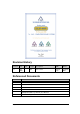
Revision History Version Date 1.
Table of Contents Chapter 1 System Objectives and Functions .................................................... 11 Purpose................................................................................................................... 11 AfiFree155i in a Computerized Flock Management System ............................ 11 AfiFree155i Stand-Alone System ..................................................................... 12 Principle of Operation and Installation ........................................
Connecting the Power Cable to a Plug-in Connection Box .............................. 42 Wiring the Solenoids .............................................................................................. 43 Wiring Solenoids to an AfiFree Connection Box .............................................. 43 Connecting Solenoids to a Plug-in Connection Box ......................................... 43 Wiring the Pulsator ..............................................................................................
Chapter 6 Corrective Maintenance ................................................................... 89 Maintenance Policy................................................................................................ 89 Silicone and Rubber Component Replacement ..................................................... 89 Replacing AfiFree155i Bodies ............................................................................... 89 Removing a Malfunctioning AfiFree body ........................................
List of Figures Figure 1: Terminal 155i units connected to AfiSheep/ AfiGoat ................................. 11 Figure 2: Terminal 155i units not connected to AfiSheep/ AfiGoat........................... 12 Figure 3: Typical AfiFree155i Layout ........................................................................ 13 Figure 4: The AfiFree Body ........................................................................................ 14 Figure 5: Terminal 155i Panel .........................................
Figure 41: AfiSheep/AfiGoat Parameters Screen ......................................................... 82 Figure 42: Parts for Attaching Vacuum Shut-Off Valve ............................................. 94 Figure 43: AfiFree body Exploded View..................................................................... 95 List of Tables Table 1: AfiFree155i Components .............................................................................. 21 Table 2: Accessories for AfiFree Connection Box Wiring.........
Manual Overview This manual contains information and instructions for a technician to mount, wire, and configure the AfiFree Body, Terminal 155i, and Wash Controller system. The manual follows the sequence of procedures for installation and configuration of the system. The appendices contain information regarding how to use AfiFree 155i, and especially Terminal 155i.
Conventions Used in this Manual Important information is highlighted in a frame, as explained below: Actions requiring special attention to avoid a possible hazard to personnel. For example, working with high voltage components. W AR NI NG C AUT IO N Actions requiring special attention to avoid possible damage to equipment or livestock. For example, avoiding the use of detergent, that may damage the AfiFree Body. NO T E Hints and recommendations for working efficiently.
Chapter 1 System Objectives and Functions This chapter contains the following sections: Purpose (below) Principle of Operation (page 12) System Components (page 21) Minimum Requirements (page 25) Purpose AfiFree155i is a milk meter and data-monitoring system that can function either as part of a computerized flock management system or as a stand-alone system. Both uses are described below.
AfiFree155i Stand-Alone System A stand-alone system is one in which the AfiFree155i milk meters are not connected to a flock management computer and software.
Figure 3: Typical AfiFree155i Layout May 2009 AfiFree Terminal 155i Installation Manual 13
AfiFree Body The AfiFree Body (Figure 4) measures the volume of milk in real time as the milk flows through it. It has a milk chamber and an electronics compartment. The milk chamber collects, measures and transfers the milk to the receiver vessel. The electronics compartment manages operation of the AfiFree Body.
Terminal 155i The user operates the AfiFree155i milk meter with the buttons on Terminal 155i. Terminal 155i also displays data about the animal being milked, such as health codes, conductivity, and milk yield.
Figure 5: Terminal 155i Panel Figure 6: Terminal 155i LCD Display 16 Chapter 1 System Objectives and Functions P/N 9040322
AfiFree Wash Controller and Wash Control Valve The parlor washing system cleans the AfiFree155i bodies via the AfiFree Wash Controller (below) and Wash Control Valve (page 17). The AfiFree Wash Controller During milking the AfiFree Body operates with a continuous flow of milk through the unit. This continuous flow does not allow the AfiFree Body to completely fill. During the cleaning cycle it is necessary to completely fill the AfiFree Body to ensure that all milk residues are washed out.
Figure 8: AfiFree Wash Control Valve Connections Boxes There are two alternative types of connection boxes for wiring AfiFree: AfiFree Connection Box (below) Plug-in Connection Box (PICB) (page 19) AfiFree Connection Box The AfiFree Connection Box (Figure 9) is a watertight junction box with terminal blocks for connecting power and communication wires.
Figure 9: AfiFree Connection Box Plug-in Wiring System The Plug-in Wiring System is an improved alternative to wiring cables to a standard AfiFree Connection Box. It saves time and wiring errors. Wiring connections are made as follows: The components of AfiFree155i connect to the Plug-in Connection Box (PICB— see Figure 10) entirely by means of ready-wired plugs and sockets. The power and communication cables (Figure 11) have extension tails that plug into the PICB for each stall.
Available spacing = 40 cm / 75 cm / 115 cm Plug-in Connection Box for stall 1 Plug-in Connection Box for stall 2 Extension Tail Extension Tail Extension Tail Cable Plug-in Connection Box for stall 3 Figure 12: Extension Tail Spacing on Power/Communication Cable Valve Installation Kit for AfiFree The valve installation kit for AfiFree contains all the parts necessary for mounting the shut-off valve and connecting it to the AfiFree Body.
System Components Table 1 shows the main components for installing the AfiFree Body and Wash Controller system. Table 2 shows accessories for AfiFree connection box wiring. Table 3 shows components of the Plug-in Wiring System (see page 19 for an explanation of the Plug-in Wiring System). Table 1: AfiFree155i Components Name AfiFree Body and Bracket Set Picture Function Catalog No.
Name Function Catalog No. Details Wash Controller Mounting Plate Required to secure Wash Controller to wall. 4088016 See page 50 The AfiFree Wash Control Valve Controls vacuum/clean air 5099010 See page 17 AfiCom1 Plus Port Complete Communication adapter between PC, AfiFree 155i, and identification system (includes AfiPort, P8 Connector Cable, and Termination Resistor) 4098550 Generic Milk Meter Bracket (optional) Distances AfiFree Body from wall. Secures AfiFree body bracket to wall.
Table 2: Accessories for AfiFree Connection Box Wiring Name Function Catalog No. Details AfiFree Connection Box Interconnection of cables 40973800 See page 18 AfiFree Body Connection Cable Connects between AfiFree155 body pigtail cable and connection box 2.8 m long 4093506 See page 38 15 m long 4093506D Connects PC. 3 lengths of junction spacing available.
Table 3: Plug-in Wiring System Name Function Plug-in Connection Box Saves wiring time and errors by enabling plugging-in of readywired connectors and cables (alternative to AfiFree Connection Box) AfiFree Body Connection Cable Connects pigtail cable of AfiFree Body Catalog No. Quantity 4097333 One per stall 2.
Name Function Power Cable Connects power supply 40 cm extension tail spacing RS485 Communication Connects PC Cable Length/ Extension Tail Spacing Catalog No.
Chapter 2 Site Preparation Requirements This chapter contains the following sections: Component Positioning Requirements (below) Physical Infrastructure Requirements (page 30) Physical Interfaces to Components (page 30) Electrical Requirements (page 30) Computer Requirements (page 32) Component Positioning Requirements This section explains the positioning requirements for the following components: AfiFree Body (below) Terminal 155i (page 28) Connection Box (page 28) Was
Terminal 155i Positioning Terminal 155i is mounted on a bracket, which can be fixed to a suitable wall or pipe. Position Terminal 155i according to the following guidelines: Where it is convenient for the milker to use the buttons and see the display With minimum exposure to animals and water Consistently throughout the parlor, so that each Terminal 155i is clearly associated with its AfiFree Body.
Wash Controller Positioning Position the Wash Controller as follows: On a wall or other location where its LEDs can be seen clearly from the parlor floor Shaded from direct sunlight (all hours of the day) and protected from water (e.g.
Physical Infrastructure Requirements The following physical infrastructure is required for operation of AfiFree155i: Milk Line Vacuum Line Washline Milk Line A stainless steel milk line is required to transport the milk to the milk tank. Vacuum Line A separate OD 50 mm PVC vacuum line is required in the parlor for the operation of the AfiFree Wash Valve. See pages 55–57 for full details of installation. Washline A separate OD 50 mm pipe is required in the parlor to wash the AfiFree155i bodies.
Electrical requirements has the following parts: Power Supply Requirements (page 31) Wiring Requirements (page 32) Grounding Requirements (page 32) Power Supply Requirements For a basic parlor installation (AfiFree155i milk meters and cluster removal pistons, without additional outputs), the power supply must meet the following requirements: 24 ± 2.4 VAC power supply, 50 VA to each milking point 24 ± 2.
Must supply power only to the AfiFree155i milk meters and to outputs operated by the AfiFree155i milk meters Do not connect either the secondary winding of the transformer or any of the loads to ground Wiring Requirements The power cables must be of sufficient size to carry the load without causing a voltage drop from the first to the last milking point. Table 5 (page 31) specifies the power cables requirements for installations with different quantities of AfiFree155i milk meters.
Chapter 3 Mounting and Wiring This chapter contains the following procedures: Checking Jumpers in the Plug-in Connection Box (below) Mounting the Connection Box (page 34) Mounting and Wiring the AfiFree Body (page 34).
Mounting the Connection Box The AfiFree Connection box has molded mounting points on its back. Two or more of these can be drilled through as required for screws or bolts. NO T E Before mounting a Plug-in Connection Box, make sure its jumpers are configured correctly (see Checking Jumpers in the Plug-in Connection Box, page 33). 1. Determine the best location for the AfiFree Connection Box or Plug-in Connection Box in accordance with Connection Box Positioning (page 28). 2.
3.
Leveling the AfiFree Body Bracket 1. Slightly loosen both leveling screws (Figure 14). 2. Place a spirit level on both arms of the bracket and level the bracket manually along the roll axis (Figure 14). 3. Place a spirit level on one bracket arm and level the bracket manually along the pitch axis (Figure 15). 4. Repeat steps 2 and 3 as necessary until the bracket is level. 5. Fasten the leveling screws securely.
Mounting the AfiFree Body The AfiFree Body has a groove on each side (Figure 4, page 14) that fits the bracket arms. 1. Make sure that the bracket locks are open on both sides of the bracket arms (Figure 16). Arm Lock Yellow Pointer (narrow side at f ront) Arm Lock Open Yellow Pointer (narrow side at back) Closed Figure 16: Bracket Lock 2. Slide the AfiFree Body into position by guiding the grooves on its sides (Figure 4, page 14) along the bracket arms; do not force the AfiFree Body into place.
Wiring to an AfiFree Connection Box 1. Plug the AfiFree Body pigtail cable into the AfiFree body connection cable (for available lengths and part numbers refer to Table 2 on page 21). 2. Route the AfiFree body connection cable to the connection box. 3. Wire the AfiFree body connection cable to the connection box according to Figure 17.
Connecting to a Plug-in Connection Box 1. Plug the AfiFree Body pigtail cable into the AfiFree body plug-in connection cable (for available lengths and part numbers see Table 3, page 21). 2. Route the AfiFree body plug-in connection cable to the PICB. 3. Plug the AfiFree body plug-in connection cable into socket 9 of the PICB.
Mounting the Terminal 155i Bracket with Bands to a Pipe 1. Determine the best location for Terminal 155i bracket in accordance with Terminal 155i Positioning (page 28). 2. Attach the Terminal 155i bracket to a pipe with suitable bands, as shown in Figure 19. Figure 19: Terminal 155i bracket attached with bands to a pipe Bolting the Terminal 155i Bracket to a Cabinet The current procedure explains how to affix the bracket to the outside of the cabinet with nuts and bolts.
1. Determine the best location for Terminal 155i bracket in accordance with Terminal 155i Positioning (page 28). 2. Mark the two horizontal holes to be drilled in the cabinet, as shown in Figure 20. 3. Drill the holes, using a 6.5 mm. drill bit. 4. Secure the Terminal 155i bracket to the cabinet with M6 bolts, lock washers, and nuts. Mounting the Terminal 155i Figure 21: Orienting Terminal 155i to its bracket 1.
Wiring Terminal 155i to an AfiFree Connection Box 1. Plug the D-connector on the Terminal 155i cable into the socket on the bottom of the Terminal 155i. 2. Route the cable to the connection box. 3. Wire the Terminal 155i cable to the connection box according to Figure 17 (page 38). Connecting Terminal 155i to a Plug-in Connection Box 1. Plug the D-connector on the Terminal 155i cable (P/N 4000400) into the socket on the bottom of the Terminal 155i. 2.
Transformer 24 VAC ( ) (0) ~ Brown Blue Hot-air Fan Power Braid Extension Kit (up to 20 m) Blue Blue Brown Brown Use connection kit for 8 AWG wire (P/N 4097376) or standard terminal Power Braid for AfiFree 1 1 Plug-in Connection Box Stall 1 Plug-in Connection Box Stall 2 Figure 22: Power Cable Wiring Wiring the Solenoids Take appropriate precautions to prevent injury from electric shock.
Connecting AfiMilk Solenoids to a Plug-in Connection Box 1. Plug the Cluster Removal Solenoid cable into socket 3 of the PICB. 2. Plug the Vacuum Shutoff, Sweep Solenoid cable into socket 4 of the PICB. Wiring Non-AfiMilk Solenoids to a Plug-in Connection Box Wire a non-AfiMilk Cluster Removal Solenoid or non-AfiMilk Vacuum Shut-off Sweep Solenoid, as follows: 1. Cut off the solenoid connection cable’s yellow wire. 2. Wire the blue and brown wires to the solenoid (Table 8). 3.
Connecting the Pulsator to a Plug-in Connection Box When connecting solenoids to a PICB, use the appropriate procedure of the following: For installations using AfiMilk solenoids—see Connecting an AfiMilk Pulsator to a Plug-in Connection Box (below) For installations using non-AfiMilk solenoids—see Wiring a Non-AfiMilk Pulsator to a Plug-in Connection Box (page 45) Connecting an AfiMilk Pulsator to a Plug-in Connection Box Plug the Pulsator cable into socket 5 of the PICB.
Installations using AfiFree Connection Boxes—see Wiring to an AfiFree Connection Box (below) Installations using AfiMilk Pre-wired External Start Buttons with PICBs—see Connecting an AfiMilk Pre-wired External Start Button (below) Installations using non-AfiMilk external start buttons with PICBs—see Connecting a Non-AfiMilk External Start Button to a Plug-in Connection Box (page 46) Wiring to an AfiFree Connection Box Wire the Cluster Removal Solenoid and the Vacuum Shut-off Sweep Solenoid to th
Wiring the Communication Cable Connect the communication cable as follows: Installations using AfiFree Connection Boxes—see Wiring to an AfiFree Connection Box (below) Installations using PICBs—see Connecting to a Plug-in Connection Box (page 48) Wiring to an AfiFree Connection Box 1. Route the communication cable from the computer to the connection boxes. 2. Wire the communication cable to the connection boxes according to Figure 17. 3.
Connecting to a Plug-in Connection Box No more than 64 milking points may be connected to the same AfiCom1 port. The communication cable must therefore be cut into lengths with no more than 64 extension tails each. Where there are more than 64 milking points, use more than one length of communication cable. NO T E 1. Install an AfiPort to the desired port of AfiCom1. 2. Connect the communication cable as in Figure 24. The last PICB in the line must have a Communication Line Termination (P/N 9030544).
Install the shut-off valve and holder as follows: When the AfiFree Body has its milk inlet on the left—see Figure 25 When the AfiFree Body has its milk inlet on the right—see Figure 26 1. Attach the Generic Shut-off Valve Holder to the generic shut-off valve bracket using the two hexagon socket screws. 2. Remove the shut-off valve from its packaging. C AUT IO N A vacuum NO operated valve must have washers between it and its holder, as in Figure 25 and Figure 26.
Vacuum NO Operated Shut-of f Valve Bolt Washer Washer M6 DIN 9021 Washer Hexagon Socket Screw Spring Lock Washer Nut Generic Shut-of f Valve Holder Generic Shut-of f Valve Bracket Air/Vacuum NC Operated Shut-of f Valve Figure 26: Mounting Shut-off Valve for AfiFree Body—Milk Inlet on Right Mounting and Wiring the Wash Controller Mounting and Wiring the Wash Controller has the following parts: Mounting the Wash Controller (below) Wiring the Wash Controller and Setting DIP Switches (page 52
To Mount the Wash Controller The Wash Controller is supplied with mounting hardware (Table 11). Table 11: AfiFree Wash Controller Hardware Description Catalog No. Quantity Allen screw, M6, 20 mm 9020383 4 Star washer 9010386 4 Nut, M6 9020212 8 1. Determine the best location for the Wash Controller in accordance with Wash Controller Positioning (page 29.) 2. Attach the mounting plates to the box as shown in Figure 27. The mounting points can be above or below the Wash Controller.
Wiring the Wash Controller and Setting DIP Switches NO T E Refer to the label on the inside of the lid for wiring and dipswitch settings. This section has the following parts: Power Input (below) Wash Control Valve Output (below) Automatic/Manual Mode Activation – Connections and Settings (below) Power Input Connect a 24 VAC (75 VA) dedicated power source to J5. Wash Control Valve Output The number of Wash Control Valves depends on the number of AfiFree155i bodies in the parlor.
Table 13: Wash Controller Activation – Connection and Settings Activation Mode Activation Type (Input Command) Connect the Command Lines to J8 Pins Jumper JP1 Pins Set DIP Switch Automatic 24V AC/DC 2, 4 1-2 4 – OFF ** Automatic Dry Contact 1, 2 2-3 4 – OFF ** Manual Wash Controller Activation Button No connections 1-2 4 – ON DSW4 * * Set the DIP switch as shown in Figure 28. ** In automatic mode DIP switch DSW3 is neutralized.
Mounting the Wash Control Valve The Wash Control Valve (Figure 8, page 18) is supplied pre-assembled. 1. Use a saddle clamp with a ¾‖ female connector to connect the Wash Control Valve to the main vacuum line (Figure 30, Detail 3). 2. Connect the solenoid to the vacuum wires in the Switch Box.
Installing the Vacuum Line for the Wash Control Valve All references in the following explanation refer to Figure 31 and Table 14. 1. Position the vacuum line (Item 1) above the milk line. Maximum length of the pipe (Item 2) is 50 cm (19‖). 2. Secure the vacuum line to the wall (or to brackets supporting the milk line) with pipe clamps (item 8). Place a pipe clamp at each milking station (to prevent the line from sagging). The vacuum line should be positioned with an angle of 1.52.
Table 14: AfiFree Wash Control Valve Vacuum Line Parts List Reference No (Figure 31) 56 Part Name P/N 1 Pipe Meridor Ø50 mm PN16 PVC 5000377 2 Pulsator pipe (single) 5100001 3 Nipple on vacuum distribution line (assembly) 5200027 4 Tee PVC cemented, 90°, 50 mm, gray 1600C0007 5 Short Reducer, PVC bush cemented,50 X 25 mm, gray 5001520 6 Hose PVC glue connector,1/2 inch X 25 mm 5000634 7 Drain valve with Ball G-12 5235571 8 Pipe clip 50 5001058 9 AfiFree wash control valve 50990
Figure 31: AfiFree Wash Control Valve Vacuum Line May 2009 AfiFree Terminal 155i Installation Manual 57
Chapter 4 NO T E System Configuration Terminal 155i supports a variety of parlor types. The Terminal 155i configurations for the various parlor types will be documented in a separate document. System configuration has the following steps: 1. Configuring AfiSheep/AfiGoat (below)—only necessary when AfiFree 155i milk meters are connected to a flock management computer 2. Configuring Milk Meters (page 61) 3. Setting Up the Wash Controller (page 70) 4. Testing AfiFree155i Performance (page 73) 5.
5.
To select number of stalls in parlor, move pointer To select parlor type, click appropriate icon Number of stalls selected Name of selected parlor type Select AfiFree milk meter icon Click here to move to next dialog box Figure 32: Parlor Configuration Dialog Box 6. Click . The Ideal Setting dialog box appears. 7. In the Ideal Setting dialog box, select the desired Ideal setting, and click OK. 8. The dialog box for the parlor type selected in step 5. Click configuration and exit.
Configuring Milk Meters Configure milk meters as follows: When AfiFree 155i milk meters are connected to a flock management computer – refer to Configuring Milk Meters in a Computerized Flock Management System, below. When AfiFree 155i milk meters are used as stand-alone units (not connected to flock management computer) – refer to Configuring Milk Meters in a Standalone System, page 68.
2. Open AfiMen. The AfiMen Real Time window (Figure 33) appears. Red fill inside a blue AfiFree155 milk meter icon indicates that the AfiFree155 milk meter is not assigned an identification number yet. AfiFree Milk Meter Icon AfiFree Milk Meter Column ID assigned and in communication No ID or communication Figure 33: AfiMen Real Time Window - Milk Tab 3. In the AfiMen Real Time window, select the Milk tab. 4. Click PARAMETER. The Milk Parameters dialog box (Figure 34) appears.
5. 6. Set two parameter values as follows: a. Automatic Address Definition - 1 b. Automatic Load Software – 0 Click OK. The AfiMen Real Time window (Figure 33) appears. 7. Select the Track tab (Figure 35). Figure 35: AfiMen Real Time Window - Track Tab 8. Make sure the milk station is in session. If the milk station is not in session, click Continue to put it in session. The system is now ready to assign identification numbers to the AfiFree 155i milk meters.
Automatic Identification Number Assignment NO T E 1. Identification numbers are assigned in the order that the AfiFree 155i milk meters are powered on and detected. Make sure to plug in the Terminal 155i’s cables in ascending order. Plug the Terminal 155i cable into the first Terminal 155i. Id-- appears on the Terminal 155i display, and identification number assignment starts automatically.
Manual Identification Number Assignment If there was a malfunction during automatic identification number assignment, or one or more identification numbers were incorrectly assigned, you can assign identification numbers manually. NO T E 1. The highest possible stall identification number is 64. On the Terminal 155i, simultaneously press display. and until Id appears on the The Terminal 155i is now in Settings mode. Id is short for Stall Identification Number.
Loading Software and Parameter Values This procedure uploads software first to the AfiFree155 body, then to the Terminal 155i. This includes upload of AfiFree 155i parameter values. NO T E If you want to change any AfiFree 155i parameter value in AfiSheep/AfiGoat from its default before uploading to the milk meter, see Entering a Parameter Value in AfiSheep/AfiGoat, page 81. For a description of the parameters, see Introduction to the AfiFree 155i Parameters, page 74. 1.
At the conclusion of software upload, each AfiFree 155i milk meter automatically enters Cleaning mode and the display shows CL followed by the stall number. Recovering from a Malfunction during Data Upload There are two options for recovery: Wait at least 5 minutes. ▪ In a shared parallel parlor, software upload restarts automatically. ▪ In a parallel parlor with entrance identification, software upload restarts after you open the exit gate.
Configuring Milk Meters in a Stand-alone System Configuring milk meters in stand-alone system has the following parts: Assigning Identification Numbers (below) Configuring the Animal Type (page 69) Assigning Identification Numbers You must assign each milk meter an identification number between one and sixtyfour. Do not give the same identification number to different milk meters. To assign an identification number: 1. Turn on the power supply to the AfiFree 155i milk meter. The display shows CL--.
Configuring the Animal Type Each AfiFree milk meter can be configured for milking one of the following animal types: Buffalo Cow Goat Sheep Make sure that each milk meter is configured for the type of animal to be milked in the parlor, by doing the following: 1. On the Terminal 155i, simultaneously press and hold down appears on the display. and until Id The Terminal 155i is now in Settings mode. Id is the first item in the Settings menu. NO T E 2. Use 3.
Setting Up the Wash Controller NO T E For parlors where the washing process is controlled by AfiWash, see AfiWash Installation manual P/N 9040646. This section contains the following parts: Wash Controller Principles of Operation (below) Wash Controller Configuration (page 70) Wash Controller Principles of Operation In milking mode, the AfiFree Body allows milk to flow through it freely. In cleaning mode, cleaning fluids must completely fill the AfiFree Body to enable thorough cleaning.
The Wash Controller has two modes of operation: Automatic mode - the main parlor wash system activates and shuts down the Wash Controller. Manual mode - the Wash Controller is activated by a manual control button, and is turned off after a predefined time interval. Wash Controller Configuration NO T E Refer to the label on the inside of the Wash Controller lid for wiring and DIP switch settings. Configuration of the Wash Controller involves setting three time parameters, explained in Table 17.
Table 18: Wash Time Intervals Measurement Parameter DIP Switch From the beginning of Cleaning Mode until the farthest* AfiFree Body is filled with liquid Time On DSW1 From the end of Cleaning Mode until the nearest* AfiFree Body is empty Time Off DSW2 * NO T E 2. ―Farthest‖ and ―Nearest‖ refer to distance from the Parlor Wash System. Set DIP switches DSW1 and DSW2 according to the time intervals measured in step 1. Figure 38 shows DIP switch positions for different time intervals.
Figure 39: DSW3—DIP Switch Options Check the current wash cycle duration by chemical testing and milk sampling. If the results are below standard, extend the wash cycle by increasing the Wash Duration parameter value. Testing AfiFree155i Performance AfiFree155i milk meters must be tested before beginning normal operation. If AfiFree155i milk meters have been installed as part of a system including antennas, parlor controls etc., the following tests are performed as part of the system tests. 1.
6. Make any necessary repairs and adjustments, and then repeat the washing cycle. 7. Check that the antennas are in communication with the AfiFree155i milk meters by bringing a spare tag into antenna rang of each antenna, and verifying that the display responds. If the tag is not assigned to an animal identification number in NO T E AfiSheep/AfiGoat, the display shows 8. 9. Before performing a milking session, check that the AfiFree155i milk meters respond to the buttons by doing the following: a.
Paramet er Paramete r Parameter description Key combi nation Min. Value Max.
Paramet er Paramete r Parameter description Key combi nation Min. Value Max.
Setting Parameters from Terminal 155i The procedures in this section make use of the information in Table 19 (page 74). Some of these parameters can also be set from AfiSheep/ AfiGoat. Reading and Setting Parameters 1. On the Terminal 155i, press the appropriate key combination specified in Table 19 (page 74). The Animal ID field displays the parameter (on the left side) and current value (on the right side). For example: . 2. To change the value, press the Edit/ Message mode button 3.
Cluster Clearance (either under AfiSheep/ AfiGoat or in a standalone configuration) Set parameter Cc to allow cluster clearance. CC parameter is the delay time desired (in seconds), between cluster removal and the lowering of the cluster. After setting this parameter, the milk meter is timed to lower the cluster (at the designated delay time) after cluster removal. After an animal has been milked and the cluster removed, the cluster remains in the lower position to allow easy preparation of the animals.
Pressing "Code"+"8" returns the milk flow to the main milk line. This feature is useful if a milker notices that here is some blood in the milk. Automatic Milk Diversion This feature automatically diverts milk from an animal that has been identified with a health code. The duration of the milk diversion depends on the code assigned to the animal: If the animal has assigned a Dump Milk Operation code, milk is diverted throughout the milking.
Auto Program Auto Program is a parameter set in AfiSheep/ AfiGoat that determines whether AfiMen automatically loads parameter values (except for the G parameter) to milk flow indicators. When Auto Program is enabled AfiMen functions as follows: 1. When communication is established with the milk meters, AfiMen compares the parameter values in each milk meter with those set in AfiSheep/AfiGoat (except for the G parameter). 2.
6. In the Password dialog box, type afi and click OK to confirm the changes. Calculating and Setting the G Parameter An AfiFree 155i milk meter provides an indication of volume of milk produced from the associated stall. However, variations in placement of the milking and vacuum lines and other factors in the parlor may cause a difference between the volume recorded by the AfiFree 155i milk meter and the actual volume produced. To compensate for this difference AfiFree 155i uses the G parameter.
The Parameters window appears. 3. Click under Station. The AfiFree 155i parameters appear in the right hand pane (see Figure 41). Figure 41: AfiSheep/AfiGoat Parameters Screen The initial values assigned to each parameter are the default values. 4. 5. Modify parameter values as follows: Integers (e.g. 8)—click the field and type the new value. Unit type (e.g. Kg)—click in the Parameter Value box to open the Unit Type menu, and select a new value. Click OK to accept the changes.
When communication is established with the milk meters, AfiMen compares the parameter values in each milk meter with those set in AfiSheep/AfiGoat (except for the G parameter). If any milk meter has a parameter with a value different from the value in AfiSheep/AfiGoat, AfiMen overwrites the value in the milk meter with the value in AfiSheep/AfiGoat (except for parameter G). To update all parameter values including the G parameter value on all AfiFree 155i milk meters: 1. Open AfiMen.
Chapter 5 Troubleshooting This chapter contains the following: Guidance on searching for the source of an electrical problem (below) Troubleshooting Guide(below) For the meaning of lit or flashing LEDs on a Terminal 155i, see Table 25: Operating Modes and their Indicators (page 97) and Table 28: Alarm and Malfunction Indicators (page 117). Searching for an Electrical Problem To search for electrical problems, proceed as follows until the problem is resolved: 1.
Table 21: Troubleshooting Guide Indication Probable cause Possible solutions AfiFree155i measures very large milk quantity Diaphragm Stuck Vacuum leak—check other units: If other units are OK, then check local vacuum line connections to AfiFree155 body If other units have similar problems then check for problems in main vacuum line Milk Overflowing AfiFree Body Defective diaphragm Check diaphragm and replace if necessary Diaphragm Stuck Vacuum leak—check other units: If other units are OK, t
Table 21: Troubleshooting Guide Indication Probable cause Possible solutions Under-weighing AfiFree Body is not level Level the AfiFree Body as described in Mounting and Wiring the AfiFree Body, page 34 Leak in the AfiFree Body resulting in penetration of air into the system Check that the cover is on securely The amount displayed is less than the actual amount of milk.
Chapter 6 Corrective Maintenance This chapter contains the following sections: Maintenance Policy (below) Silicone and Rubber Component Replacement (below) Replacing AfiFree155i Bodies (below) Replacing a Terminal 155i (page 90) Maintenance Policy Upgrades and changes to the software should be carried out by SAE Afikim trained technicians only.
Installing a Replacement AfiFree body 1. Mount the new AfiFree body as in Mounting the AfiFree Body (page 37). 2. Connect the hoses to the new AfiFree body. 3. Connect the pig-tail of the new AfiFree body to the AfiFree body connection cable. Replacing a Terminal 155i C AUT IO N When replacing several Terminal 155i’s, always start with the malfunctioning unit that has the lowest identification number.
Automatic address definition Automatic Load Software Automatic Load Tables A parameter is enabled when its value is 1. 7. To accept the settings, press OK. Removing a Malfunctioning Terminal 155i 1. Unplug the Terminal 155i cable from the Terminal 155i. 2. Push the Terminal 155i up, until the top clip is above the bracket. 3. Using two hands, pull the Terminal 155i towards you, freeing it from the bracket. Installing a Replacement Terminal 155i 1.
Check diaphragm is properly inserted into its seat. 5. Vacuum line to washing valve diaphragm of AfiFree155 body (including the line’s branches)—check for defects. 6. Main vacuum valve—check for defects. 7. AfiFree Wash Controller—check for faults. 8. Clusters, liners, and shut-off valves or diaphragms—check for defects and replace as necessary. 9. Pulsators—check for defects and replace as necessary. 10.
Chapter 7 Parts Lists This chapter contains the following parts lists: Vacuum Shut-Off Valve Installation—Replacement Parts List (below) AfiFree Body—Replacement Parts List (page 95) Terminal 155i—Replacement Parts List (page 96) Vacuum Shut-Off Valve Installation— Replacement Parts List The AfiFree155i milk meter controls a valve that shuts off vacuum to the cluster. When an animal has finished milking, this valve is closed and vacuum to the teat chamber of the cluster is shut off.
1 6 2 7 8 3 9 4 5 10 11 Figure 42: Parts for Attaching Vacuum Shut-Off Valve Table 22: Shut-Off Valve Installation—Replacement Parts List No.
AfiFree Body—Replacement Parts List Figure 43 shows the replacement parts of the AfiFree body. Table 23 lists the part names and part numbers. Figure 43: AfiFree body Exploded View Table 23: AfiFree body Replacement Parts List No.
Terminal 155i—Replacement Parts List Table 24 lists the replacement parts for Terminal 155i. Table 24: Terminal 155i Replacement Parts List Part 96 Catalog No.
Appendix A User Information and Instructions This appendix contains the following sections: Terminal 155i Modes and Settings (page 97) Terminal 155i User Procedures (page 99) Terminal 155i Display Fields (page 104) Terminal 155i Alarms (page 116) Terminal 155i Modes and Settings This section deals with modes and settings of the Terminal 155i, as follows: Operating Modes (below) Terminal 155i Settings (page 98) Operating Modes (See footnotes to tables regarding configurations under
Changing Operating Mode Table 26 shows how to change the operating mode of the Terminal 155i.
Viewing and changing the Animal Type Use this procedure under standalone configuration. (Under AfiSheep/ AfiGoat, the animal type is set from within the flock management system.) 1. While holding down the Animal ID button , press 0. The Animal ID field displays the current animal type, according to the following key: ▪ CO — cow ▪ SHEEP — sheep ▪ GOAt — goat ▪ BUFF — buffalo ▪ WTEST — salt water test mode 2. 3. To change the value, do the following: a. Press the Edit/ Message mode button . b.
Displaying/Hiding Animal Identification Number To display the animal identification number of the animal last identified in the stall, press for more than two seconds. To hide the animal identification number after it has been displayed, press . Message Sub-Mode Procedures (All of the procedures in this section are relevant under AfiSheep/ AfiGoat only.) You activate the message sub-mode by pressing the Terminal 155i Edit/ message mode button .
2 or A or B or C example 2 Key pressed Time pressed First 2 seconds Next 1 second Next 1 second Next 1 second Next 1 second Animal ID field The only valid position for an alphabetical character is the first (left-most) position. The best way for typing of number with the letter is to key in a letter first and just after that to type a numerous part of ID. Six-digit alphanumeric example This example illustrates entering animal ID B4362.
Managing Health, DIM, Activity, and Days from Insemination Parameters Use this message for changing, entering or canceling one or more of the following parameters: Health code Days-in-milk (DIM) Activity/ Days from insemination 1. On the Terminal 155i, press the Edit/ Message mode button . The message sub-mode is activated. 2. Do the following for each parameter that you need to modify: a. Press the health code button . The health code field blinks with hyphens b. .
While the data is being processed, the data updating icon flashes. Following successful processing, the message mode is deactivated.
Terminal 155i Display Fields Display Fields under AfiSheep/ AfiGoat Display fields under AfiSheep/ AfiGoat connection 1. Milk Yield field Mode Milk Yield field displaying Example Celsius Cleaning The Temperature inside of Milk Meter Body Fahrenheit Hyphen (before first milking or after reset) Removal Final milk yield (at end of previous milking before reset) On-Line Milk Yield updated every 100mSec(?) Milking 2.
3. Last Highest Conductivity Mode Description Example OFF if no fluid in a milk meter Cleaning The Current Conductivity of the cleaning fluid in AfiFree conductivity units (updated every 3 sec end calculated by average conductivity of last 3 sec) OFF (before first milking or after reset) Removal The Maximum Conductivity of the milk at last milking in AfiFree conductivity units Milking The Maximum Conductivity of the milk at current milking in AfiFree conductivity units 4.
5. Expected Milk Yield field Mode Description Cleaning OFF Example Predicted yield (after identification) Removal OFF (when no identification) Predicted yield (after identification) Milking 6. Days in Milk field Mode Description Cleaning OFF Example Days in milk (after identification) Removal OFF (when no identification) Days in milk (after identification) Milking 7.
Mode Description after identification Removal Milking when no identification after identification Example Days from insemination (after identification) OFF (when no identification) Days from insemination (after identification) 8. Momentary Flow field Mode Description Cleaning OFF Removal OFF Milking Current milk flow Example 9.
10. Milking Time Clock field Mode Description Cleaning OFF Example OFF (before first milking or after reset) Removal Last milking duration (at end of previous milking before reset) Milking Time from start of current milking (min:sec) *When milking time reaches 20 min the counting restarts from 0:00 and the first character blinks. 11. Pulsation field Mode Removal Cleaning Milking Description Pulsation Output 1 Pulsation Output 2 OFF OFF ON OFF OFF ON ON ON Example 12.
13. Group field Mode Description Cleaning OFF Example Group number (after identification) Removal OFF (when no identification) Group number (after identification) Milking 14.
15. Health code field Mode Description Cleaning OFF Example Health code (after identification) Removal Milking OFF (when no identification) If an animal has two health codes, the second code is displayed on the "Peak flow" field. If an animal has three health codes, the third code is displayed on the "Momentary flow" field. In both those cases the icon of flow fields and flow bar are deactivated. 16. Icon PC Mode Description Message sub-mode OFF OFF Message sub-mode ON ON Example 17.
Display Fields under Standalone Configuration 1. Milk Yield field Mode Milk Yield field display Example Celsius Cleaning The Temperature inside of Milk Meter Body Fahrenheit Hyphen (before first milking or after reset) Removal Final milk yield (at end of previous milking before reset) On-Line Milk Yield updated every 100 mSec Milking 2. Animal ID field Mode Description Example Cleaning Removal OFF Milking 3.
Mode Description Milking The Maximum Conductivity of the milk at current milking in AfiFree conductivity units Example 4. Predicted conductivity field Mode Description Cleaning Removal Milking OFF Example 5. Predicted yield field Mode Description Cleaning Removal Milking OFF Example 6. Days from insemination field Mode Description Cleaning Removal Milking OFF Example 7.
8. Current milk flow rate field Mode Description Cleaning OFF Removal OFF Milking Current milk flow Example 9. Peak milk flow rate field Mode Description Cleaning OFF Example OFF (before first milking or after reset) Removal Last milk flow peak (at end of previous milking before reset) Milking Last milk flow peak 10.
11. Pulsation field Mode Cleaning Description Pulsation Output 1 Pulsation Output 2 OFF OFF ON OFF OFF ON ON ON Example Removal Milking 12. Stall number field Mode Description Cleaning, Removal, Milking Stall number Example 13. Group field Mode Description Cleaning, Removal, Milking OFF Example 14. Infected Half field Mode Description Cleaning, Removal, Milking OFF Example 15.
16. Icon PC Mode Description Message sub-mode OFF OFF Example 17.
Terminal 155i Alarms Alarm and Malfunction Indicators Terminal 155i indicates an alarm or malfunction by flashing or continuously lit LEDs (green and red). The animal has a code defined in AfiSheep/ AfiGoat as a "High level health code ".
Diaphragm fault Diaphragm not open No Milk Meter The communication with milk meter is lost Coincident al During the milking Coincident al "Stall number" field is blinking and "Animal ID" field blinks with NO YES "Stall number" field is blinking and "Animal ID" field blinks with NO YES "Stall number" field is blinking and "Animal ID" field blinks with NO YES Remark: To cancel any visual or sound alarm, press simultaneously "Cancel" and "0".
Appendix B Milking System Cleaning Guidelines This appendix provides guidelines and recommendations for cleaning the milking systems. It contains the following sections: Cleaning Recommendations (below) Performing an Acid Wash (page 120) Always comply strictly with the instructions of the chemical manufacturers. Failure to comply with instructions can cause injury and damage to equipment. Use gloves and protective goggles when working with chemical detergents.
Chemical Dispensing Pumps To achieve accurate detergent dispensing, we recommend using chemical dispensing pumps. Vacuum Pump The vacuum pump must operate throughout the cleaning cycle. A temporary stop of the vacuum pump while the sink is being filled can cause milk and cleaning fluid to seep out between the lid and the AfiFree155 body. The clusters must be connected to the jetters.
After warming up, the milking system must be brought into a closed circulation setup, detergent added, and the hot water and detergent circulated for 10-12 minutes. After being circulated in the milking system, the hot water and detergent must be drained away. Rinsing with cold water: the milking system must be rinsed with cold water in an open circuit to remove all traces of detergent. Cleaning Exterior Surfaces C AUT IO N Detergents are destructive.