
Installation Guide
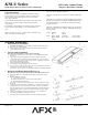

KNLU Series LED Under Cabinet Fixture
Models KNLU9, KNLU14, KNLU22, KNLU32 & KNLU40 Plug-in or Hard Wire, Linkable
Page 1 of 2 8060793 REV1
Safety Precautions
Read all safety precautions and installation instructions carefully
before installing or servicing this fixture. Failure to comply with
these instructions could result in potentially fatal electric shock
and/or property damage.
It is recommended that a qualified electrician perform all wiring. This
fixture must be wired in accordance with all national and local
electrical codes.
Do not handle an energized fixture or attempt to energize any fixture
with wet hands or while standing on a wet or damp surface or in
water.
Make sure that the power source conforms to the requirements of the
fixture. (See labels on fixture housing).
To reduce the risk of electrical shock, and to assure proper operation,
this fixture must be adequately grounded.
This fixture is designed for use only in a 110-120VAC, 60Hz fused
circuit.
This fixture is to be used for general indoor lighting, and suitable for
damp locations. Linkable total wattage is 500 Watts. Dimmers have
wattage limits and they vary and need to be followed when using
long runs of fixtures.
This fixture is dimmable in the high (II) setting only. The following
dimmers are approved for use to achieve smooth dimming down to
10% of full scale:
Leviton – DZMX1 6674
6672 6681W
Lutron – DWCL 153PH CT-603PG TGCL-153PH
MACL 153MH DVCL-153P DVELV-300P
S-600P
Assembly Instructions
1. Preparation for Installation
A. Disconnect electrical power before installing or servicing any part of this fixture.
B. Place fixture on a clean flat surface.
C. Determine input power connection method (Cord, Hardwire or Link) and follow
corresponding directions below.
2. Cord to Outlet Installation
(Skip this step if using Hardwire or Link-to-Fixture Installation)
A. Fixture must be mounted within 5’ of an outlet. Power cord NOT included (Sold
Separately).
B. Connect Cord to fixture by snapping the quick connect end of the cord to the
corresponding connector in the end of the fixture marked “IN”. The cord will only
connect to the “IN” connector so make the right connector is identified. Do not force
the connection, it should snap in easily.
C. Follow the directions for Mounting below.
D. Once Mounting is completed, plug the cord into the outlet.
E. The unit can now be turned on with the Power switch (7a). By flipping the switch (7a)
select between one of the 3 modes (Lo, Off, Hi ).
Switch (6a) is used to change the color temperature of light delivered 2700K, 3000K & 4000K CCT respectively.
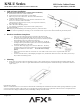
3. Hardwire Installation Preparation (Figure 2)
(Skip this step if using Cord to Outlet or Link-to-Fixture Installation to Power Unit)
A. Remove appropriate 3/8” diameter knockout for supply wiring entry and remove
plug (1).
B. Determine appropriate connector:
i) Cable connector is included.
ii) Flexible conduit BX (AC) 3/8”trade size cable (not included).
iii) Anti-short bushing (not included).
C. Insert cable connector (3) into the housing open hole. Screwing it into the nut in the
bracket (4).
D. Determined the length of BX cable and add about 5” or an appropriate length for the
stripping purposes. Cut the required length of the cable. Trim away the insulation.
Push the exposed wires (hot, neutral and ground) through the anti-short bushing and
slide this bushing all the way down to the exposed wires until it is snug up against
the armor.
E. Remove screw holding on back cover plate and remove cover (5) and discard.
F. (See Hardware Installation Completion) for image (6)
G. Snap bracket into main housing and tighten screw back in to hold into position.