Precision Farming System Operators Manual
General PFadvantage Ag Leader Technology Welcome Welcome to the Ag Leader Technology family. Ag Leader Technology is dedicated to the development of advanced, yet practical and cost-effective tools for grain production. Above all, however, we are dedicated to meeting your needs for support of existing products and development of product improvements.
General PFadvantage Ag Leader Technology Limited Warranty Ag Leader Technology will repair or replace at no charge any component of the PFadvantage system that fails during normal service on the equipment model that the system was intended for use within two years from the warranty start date. The warranty start date will initially be set to the date on which your product is shipped from Ag Leader Technology.
General PFadvantage Ag Leader Technology General Description The PFadvantage is a universal monitor/controller for crop production. It can be transferred from a combine to a tractor or other vehicles easily. In the combine it functions as a yield monitor and accurately measures and records acres, moisture, grain weight, bushels, and yield on-the-go. In the tractor or sprayer it connects to a sprayer or planter controller and monitors and controls the application rate.
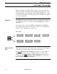
General PFadvantage Ag Leader Technology Display Selection Keys Memory Card Slot (On side of PFadvantage) Power Switch Arrow Keys Menu Key Area Count Switch Menu Selection Keys Figure 1: Front panel of the PFadvantage Arrow Keys The UP, DOWN, LEFT and RIGHT ARROW keys on the right side of the keypad are used to select and change a setting. The bottom LEFT and RIGHT ARROW keys are only used to view more menu or display items. They are never used to select or change a setting.
General PFadvantage Ag Leader Technology Display and Display Selection Keys The PFadvantage has four display lines for viewing items on the main operating screen. You can choose which items you see on the display and the position that the items appear on the display. To change a display item on a display line you must select the line. The four display selection keys to the right of the display each select a display line. A rectangular box surrounds the display line to show that it is selected.
General PFadvantage Ag Leader Technology When some display items (like swath) are selected, an up and down arrow symbol will appear on the right of the display line. This indicates you can change the setting of the item with the UP or DOWN ARROW keys. After you have made the change you must press the key to the right of the display line to deselect the line. Menu Key The MENU key switches the menus on the bottom of the display. There are two main menus that you can view by pressing the MENU key.
General PFadvantage Ag Leader Technology Area Count Switch The area count switch manually turns on and off area counting. When the switch is in the up position area is counting. When the switch is in the down position, area is not counting. The monitor will display either “AREA ON” or “AREA OFF” on the bottom right corner of the display to indicate the status of area counting. Connectors The PFadvantage has six connectors on the back of the console.
General PFadvantage Ag Leader Technology Grain Flow Sensor Below is an example of a grain flow sensor. Your grain flow sensor may look different, depending on which combine model you have. On all combines, the grain flow sensor installs on top of the clean grain elevator. The grain flow sensor measures the grain weight in pounds as you harvest. The clean grain paddles throw the grain, as the paddles rotate around the top sprocket, toward the grain flow sensor.
General PFadvantage Ag Leader Technology Moisture Sensor Below is an example of the moisture sensor mounted on the side of a clean grain elevator. The moisture sensor is installed in the elevator mount kit.
General PFadvantage Ag Leader Technology Header Height Sensor Below is an example of a header height sensor installed underneath a combine cab. The header height sensor tells the monitor the position of the combine head so that when the head is raised on the end rows, the monitor stops counting area.
Setup Overview PFadvantage Ag Leader Technology Important Notices The PFadvantage must be set up before field operation, but before you begin the setup procedures, read the following notices: The PFadvantage is a software upgradeable monitor. Ag Leader Technology will periodically offer free operating program upgrades to increase the capabilities of the PFadvantage. Operating program upgrades will be available as Internet downloadable files from the Ag Leader web site. Internet http://www.agleader.
Setup Overview PFadvantage Ag Leader Technology Item New Leader Mark III/Mark IV Flexicoil Flexcontrol Hiniker 8605 Teejet 844 Flowmeter Controller Direct Drive Controller for Rawson Accu-Rate model controllers Using Power Supply 2-2 Operating Mode Application Rate Application Rate Application Rate Application Rate Application Rate Application Rate Page 2-73 2-79 2-85 2-91 2-95 2-100 The PFadvantage console does not need to be in the vehicle to set it up.
Setup Overview All Modes PFadvantage Ag Leader Technology Order of Keys (Harvest Mode) Press the MENU key the display. SUMMARY until you see the following keys on CAL SETUP DIAG Press the SETUP key to view the following setup menu items. SETUP OPTIONS PRESS TO EXIT SWATH MARKS GRAIN CARD LOAD VEHICLE CONSOLE MEMORY GPS MAP Press the bottom LEFT or RIGHT ARROW keys to switch between and view the setup menu items shown above.
Setup Overview All Modes Order of Keys (Site Verification Mode) PFadvantage Ag Leader Technology Press MENU key the display. CAL Until you see the following keys on the SETUP DIAG Press the SETUP key to view the following setup menu items. SETUP OPTIONS PRESS TO EXIT SWATH MARKS CARD LOAD VEHICLE CONSOLE MEMORY GPS MAP Press the bottom LEFT or RIGHT ARROW keys to switch between and view the setup menu items shown above.
Setup Overview All Modes PFadvantage Ag Leader Technology Order of Keys (Application Rate Mode) Press the MENU key the display. CAL until you see on the following keys on SETUP DIAG Press the SETUP key to view the following setup menu items. SETUP OPTIONS PRESS TO EXIT APP.RATE CONFIG MARKS CARD LOAD CONSOLE MEMORY GPS MAP Press the bottom LEFT or RIGHT ARROW keys to switch between and view the setup menu items shown above.
Console Setup All Modes PFadvantage Ag Leader Technology Introduction The console settings are general settings that apply to all operating modes and uses of the PFadvantage.
Console Setup All Modes PFadvantage Ag Leader Technology Operating mode The PFadvantage has the following operating modes: Grain Harvest, Grass Seed Harvest, Cotton Harvest, HarvestMaster™, Application Rate and Site Verification. Upon changing the operating mode you should make sure all setup items for that operating mode are correct. To switch modes, you must install that modes operating firmware. The exception is Site Verification Mode. Site Verification is available with all other modes.
Card Setup All Modes Introduction PFadvantage Ag Leader Technology If you are using a GPS receiver, all the GPS data must be logged to a memory card. If you are not using a GPS receiver, you do not need a card. The memory card must be formatted with a DOS format. Ag Leader cards rarely need to be formatted since they are usually DOS formatted before they are shipped. If formatting is required, format the card in your PC before using.
Card Setup All Modes PFadvantage Ag Leader Technology FILES OPTIONS File Name File Size Last Modified Date COPY TO FILE Changing a Setting Step 1 2 3 Logging Device 02081501.YLD 132640 bytes 13:42 08/15/2002 RESTORE FILE ERASE FILE EXIT Action Use the UP or DOWN ARROW keys to select the item you want to change. The item is selected when a black filled rectangular box surrounds the entire line. Press the EDIT key and then use the UP or DOWN ARROW keys to change the number or setting.
Card Setup All Modes PFadvantage Ag Leader Technology Ag Leader 32MB ATA Flash Card Logging Hours Available/Logging Interval 1 sec 2 sec 3 sec 400 800 1200 NOTE: The logging hours available can vary from the numbers shown above due to the number of separate files that can be stored on the card. Log File The PFadvantage requires a log file to store data on a memory card. Harvest, Site Verification and Application rate mode log files will have a “.yld” extension.
Card Setup All Modes PFadvantage Ag Leader Technology Copying Data to Log File To copy memory to log files that are not set as the current log file, press the SHOW FILES key and select one of the log files. Press the FILE OPTIONS key and press the COPY TO FILE key. At the card setup screen, press the COPY TO CARD key to copy memory to the file set as the log file (this is the same copy to card function that automatically occurs when monitor is shut off).
Creating, Naming Fields, Loads All Modes except App Rate Recommendations PFadvantage Ag Leader Technology NOTE: If using Application Rate Mode, refer to the Controller Setup instructions on how to create and change fields. Refer to this section for how to name fields and loads. All the information recorded by the PFadvantage must be recorded in a field and load. The field and load that the monitor is set on is located on the top line of the display on the main operating screen.
Creating, Naming Fields, Loads All Modes except App Rate PFadvantage Ag Leader Technology Creating and Naming Fields Step 1 Action Press the MENU key until the following is displayed on the bottom of the display. FIELD 2 SHOW MAP LOAD OPTIONS Press the FIELD key twice to view the screen below.
Creating, Naming Fields, Loads All Modes except App Rate Step 5 6 PFadvantage Ag Leader Technology Action Creating Fields Press the UP ARROW key to scroll through all the fields. Once you scroll past the last field, “Create New Field” will be displayed. Name the field and set the grain or site type, then with “Create New Field” displayed above the field number press the ACCEPT key to create the new field. Repeat Step 5 and create and name all your fields.
Creating, Naming Fields, Loads All Modes except App Rate PFadvantage Ag Leader Technology Creating and Naming Loads Step 1 Action Press the MENU key until the following is displayed on the bottom of the display. SHOW OPTIONS MAP Press the LOAD key twice to view the screen below.
Creating, Naming Fields, Loads All Modes except App Rate Step 4 5 PFadvantage Ag Leader Technology Action Creating Loads Press the UP ARROW key to scroll through all the loads in the field for the grain type. Once you scroll past the last load, “Create New Load” will be displayed above the load number and name. Name the load for the displayed grain/site type, then with “Create New Load” displayed above the load number press the ACCEPT key to create the new load.
Marker Setup All Modes PFadvantage Ag Leader Technology Introduction If you are using an external Field Marker ignore the instructions below. The marker setup screen is only used for making settings for the Internal marker selection keys. IMPORTANT: If you are using the external field marker, make sure that under the CONSOLE key you set Field Marker to EXTERNAL.
Marker Setup All Modes Changing a Setting PFadvantage Ag Leader Technology Step 1 2 3 4 Action Use the UP or DOWN ARROW keys to select the mark. The mark is selected when a black filled rectangular box surrounds the entire line. Press the EDIT NAME key to rename an existing mark. Use the UP or DOWN ARROW keys to change a character in the name. Use the LEFT or RIGHT ARROW keys to move the cursor over another character within the name. Press the ACCEPT key after you have changed the name.
GPS Setup All Modes PFadvantage Ag Leader Technology Introduction The GPS 4100 and GPS 1000 require no initial setup to begin fieldwork. The PFadvantage will display a “D” or “G” on the top right hand corner of the display to indicate a GPS signal. A “D” indicates that you have a differential signal. A “G” indicates that you have a GPS signal and you GPS receiver are tracking four or more satellites.
GPS Setup (All Modes) PFadvantage Ag Leader Technology GPS SETUP NMEA MESSAGE GPS INPUT/OUTPUT BEACON DIFFERNTIAL SATELLITE DIFFERENTIAL LIGHTBAR GUIDANCE EDIT EXIT Figure 3. GPS SETUP Screen Step 3 Action At the GPS SETUP screen (Figure 3) scroll down to Satellite Differential Mode with down arrow key and press EDIT. You should now see the screen shown in Figure 4. SATELLITE DIFFERENTIAL SETUP Differential Source WAAS Differential Provider Satellite Frequency 0000.
GPS Setup All Modes PFadvantage Ag Leader Technology Satellite Selection If you will be using the satellite differential option then do the following depending on which service provider you select. Step 1 Action Press Menu key on PFadvantage until SETUP is displayed, press SETUP key. Press bottom left or right arrow key until GPS is displayed and press GPS key. At the GPS SETUP screen scroll down to Satellite Differential with down arrow key and press EDIT.
GPS Setup (All Modes) PFadvantage Ag Leader Technology SATELLITE DIFFERENTIAL SETUP Differential Source Satellite Differential Provider Omnistar Satellite Frequency 0000.0000 Satellite Baud Rate 0000 Provider User Code 0 OMNISTAR Code 00000000000000000000000000 ACCEPT If you will be using… Omnistar 2-22 CANCEL Then… At SATELLITE DIFFERENTIAL SETUP screen Differential Source will be highlighted, press EDIT key and use up or down arrow key until Satellite is displayed and press ACCEPT key.
GPS Setup All Modes PFadvantage Ag Leader Technology SATELLITE DIFFERENTIAL SETUP Oministar Satellite Beacon Frequencies: Eastern USA 1556.825 Central USA 1554.497 Western USA (1) 1551.429 Western USA (2) 1551.489 Australia 1558.510 Europe 1531.230 South America (1) 1541.705 South America (2) 1541.715 Custom (1) 0000.0 Custom (2) 0000.
GPS Setup All Modes PFadvantage Ag Leader Technology SATELLITE DIFFERENTIAL SETUP Oministar Satellite Beacon Frequencies: Eastern USA 1556.825 Central USA 1554.497 Western USA (1) 1551.429 Western USA (2) 1551.489 Australia 1558.510 Europe 1531.230 South America (1) 1541.705 South America (1) 1541.705 Custom (1) 0000.0 Custom (2) 0000.
GPS Setup All Modes PFadvantage Ag Leader Technology SATELLITE DIFFERENTIAL SETUP Differential Source Satellite Differential Provider RACAL Satellite Frequency 1553.345000 Satellite Baud Rate 1200 Provider User Code 8111 OMNISTAR Code 00000000000000000000000000 ACCEPT If you will be using … THALES (RACAL) CANCEL Then… At SATELLITE DIFFERENTIAL SETUP screen Differential Source will be highlighted press EDIT key and use UP or DOWN ARROW key until Satellite is displayed and press ACCEPT key.
GPS Setup All Modes PFadvantage Ag Leader Technology SATELLITE DIFFERENTIAL SETUP RACAL Satellite Beacon Frequencies: North American East 1553.345 North American Mntn 1554.350 North American West 1556.225 Australia 1558.525 Europe 1531.210 South Africa 1552.640 Custom (1) 0000.0 Custom (2) 0000.0 Custom (3) 0000.0 Custom (4) 0000.0 ACCEPT CANCEL SATELLITE DIFFERENTIAL SETUP RACAL Satellite Beacon Frequencies: North American East 1553.345 North American Mntn 1554.350 North American West 1556.
GPS Setup All Modes PFadvantage Ag Leader Technology SATELLITE DIFFERENTIAL SETUP Differential Source Satellite Differential Provider RACAL Satellite Frequency 1553.345000 Satellite Baud Rate 1200 Provider User Code 8111 OMNISTAR Code 00000000000000000000000000 ACCEPT Beacon Selection CANCEL The settings for beacon selection are Auto range, Auto Power and Manual. • Auto Range: This is the default setting.
GPS Setup All Modes PFadvantage Ag Leader Technology GPS SETUP NMEA MESSAGE GPS INPUT/OUTPUT BEACON DIFFERNTIAL SATELLITE DIFFERNTIAL LIGHTBAR GUIDANCE EDIT Step 3 4 EXIT Action From the GPS SETUP screen scroll down to BEACON DIFFERNTIAL and press EDIT key. Use up or down arrow keys to set mode. After setting Auto Power mode, push ACCEPT key and then EXIT.
GPS Setup All Modes PFadvantage Ag Leader Technology BEACON SETUP Mode: Channel 0 Frequency Channel 1 Frequency Manual 300.0 300.0 ACCEPT Step 5 6 EXIT Action If you are setting to Manual push ACCEPT key then use down arrow key to scroll to Channel 0 Frequency and press EDIT key. Use the up or down arrow key to set desired frequency and press ACCEPT key. Scroll down to Channel 1 Frequency and press EDIT key. Use up or down arrow keys to set desired frequency and press ACCEPT key.
Vehicle Setup Harvest Mode PFadvantage Ag Leader Technology Introduction For each operating mode, there are different items to setup in the vehicle setting screen. Below are the setup items for the harvest mode. Refer to your Initial Calibration Sheet to make the correct settings.
Vehicle Setup Harvest Mode PFadvantage Ag Leader Technology Step 1 Changing a Setting 2 3 Action Use the UP or DOWN ARROW keys to select the item you want to change. The item is selected when a black filled rectangular box surrounds the entire line. Press the EDIT key and then use the UP or DOWN ARROW keys to change the number or setting. Once you have changed a setting press the ACCEPT key. Press the EXIT key once you have made all the settings.
Vehicle Setup Harvest Mode Area count stop beeps PFadvantage Ag Leader Technology This setting is for the number of times the monitor beeps when the head is raised at the end of a pass and the monitor stops counting area. NOTE: The recommended setting is 20. Set this number high enough so that after the head is raised at the end of a pass, the beeps continue until the combine is completely turned around and the head is lowered to start the new pass.
Vehicle Setup Harvest Mode PFadvantage Ag Leader Technology Primary and Secondary speed sensor The monitor has four different primary speed settings. They are listed below. Ground Speed Sensor Speed sensor on transmission Speed sensor on tracks Radar gun GPS receiver Primary Speed Sensor WHEEL TRACK RADAR GPS If you choose GPS as your primary speed sensor, you need to set the secondary speed sensor to WHEEL, TRACK, or RADAR. If the GPS signal is lost, the monitor will use the secondary speed sensor.
Grain Setup Harvest Mode PFadvantage Ag Leader Technology NOTE: Grass Seed monitors are setup using the same procedures as Grain.
Grain Setup Harvest Mode PFadvantage Ag Leader Technology Changing a Setting Step 1 2 3 4 Action Use the UP or DOWN ARROW keys to select the grain. The grain is selected when a black filled rectangular box surrounds the entire line. Press the EDIT SETTINGS key to move to another screen and change the settings for the selected grain. Refer to the screen below. Press the EDIT NAME key to rename an existing grain (can not rename SOYBEANS, CORN, or WHEAT).
Grain Setup Harvest Mode PFadvantage Ag Leader Technology Dry lbs / bu This setting is the pounds / bushel value that the monitor uses to calculate bushels. You can change this setting for all grains except corn (56 lbs / bu), soybeans (60 lbs / bu) and wheat (60 lbs / bu). Dry moisture This setting is the moisture value that the monitor uses to calculate dry bushels. Example: Corn – 15% Soybeans – 13% Scale Factor For grass seed the recommended setting is 1. Settings are 1, 10, 100.
Grain Setup Harvest Mode PFadvantage Ag Leader Technology Changing C11 Step 1 Action You must display the weight calibration screen. Press the following keys to view the weight calibration screen: MENU key CAL key WEIGHT key 2 3 4 5 6 Refer to the screens on the next page and press the UP or DOWN ARROW keys to set a grain type that you will harvest. Press the SHOW CAL NUMBERS key.
Grain Setup Harvest Mode PFadvantage Ag Leader Technology GRAIN CALIBRATION SELECT GRAIN: SOYBEANS ENTER WEIGHT SHOW CAL LOADS SHOW CAL NUMBERS EXIT GRAIN CALIBRATION: SOYBEANS CALIBRATION NUMBERS C1 C2 C3 C4 C5 C6 C7 C8 C9 C10 C11 EDIT 0 250 500 750 1000 1250 1500 1750 2000 2250 2500 CAL ON/OFF PERFORM CAL ACCEPT CANCEL *** 2-38 EXIT September 2003
Swath Setup Harvest Mode PFadvantage Ag Leader Technology Introduction The swath setup screen is used to set the permanent, full swath of your head. Do not adjust the swath setting on this screen when you encounter a partial swath while harvesting. Refer to the Swath Setting instructions in Operation Section and select swath as a display item and set a partial swath.
Swath Setup Harvest Mode PFadvantage Ag Leader Technology Changing a Setting Step 1 2 3 4 Action Use the UP or DOWN ARROW keys to select the grain. The grain is selected when a black filled rectangular box surrounds the entire line. Press the EDIT # ROWS key to change the number of rows. Use the UP or DOWN ARROW keys to change the number. Press the ACCEPT key after you have changed the number. Press the EDIT SPACING key to change the row spacing. Use the UP or DOWN ARROW keys to change the number.
Swath Setup Site Verification Mode PFadvantage Ag Leader Technology Introduction The swath setup screen is used to set the permanent, full swath of your application equipment. Do not adjust the swath setting on this screen when you encounter a partial swath in the field. Refer to the Swath Setting instructions in Operation Section and select swath as a display item and set a partial swath. NOTE: If you do not want to count area, you do not need to set the swath.
Vehicle Setup Site Verification Mode PFadvantage Ag Leader Technology Introduction For each operating mode, there are different items to setup in the vehicle setting screen. Below are the setup items for the site verification mode.
Vehicle Setup Site Verification Mode PFadvantage Ag Leader Technology Press the UP or DOWN ARROW key to scroll down to highlight a setting and press the EDIT key to change a setting, then press ACCEPT key. After making changes, press EXIT key. Choose the vehicle you want to use and press ACCEPT VEHICLE key. Area count stop beeps This setting is for the number of times the monitor beeps when the monitor stops counting area at the end of a pass.
Raven Controller (with Serial Port) Application Rate Mode PFadvantage Ag Leader Technology NOTE: If your Raven console has a serial port, it will be on the back of the console. It is a nine-pin rectangular computer port. The Raven 750 and 760 serial port is built-in the main wiring harness. Not all Ravens consoles have a serial port. Cable attachment for Raven controllers with serial ports PFadvantage Port 3 Raven Serial Cable (p.n. 2000944) ATV Battery Power Cable (p.n.
Raven Controller (with Serial Port) Application Rate Mode PFadvantage Ag Leader Technology APP RATE CONFIG PRODUCT CONTROLLER Treflan 440 Roundup 440 EDIT SETTINGS CREATE NEW DELETE CHANNEL Rate 1 Rate 1 EXIT Press CREATE NEW key to set up a new configuration or select an existing configuration and press the EDIT SETTINGS key. A new screen appears with the following settings. Select each setting and press EDIT key to change the settings. Controller Make: Set to RAVEN.
Raven Controller (with Serial Port) Application Rate Mode PFadvantage Ag Leader Technology App Distance From GPS: Set to distance between where product exits applicator and position of GPS antenna on vehicle. Example: If spray boom is 20 feet behind GPS antenna set to 20 feet back. Press DOWN ARROW key to set feet back, UP ARROW key to set feet forward. Full Swath: Ignore setting. Swath automatically comes from serial port of Raven.
Raven Controller (with Serial Port) PFadvantage Application Rate Mode Ag Leader Technology Avg.
Raven Controller (with Serial Port) Application Rate Mode PFadvantage Ag Leader Technology Actual Rate Units: Ignore this setting. Log Actual Rate: Set to YES to log actual rate to card. Set to No, otherwise. 4. This completes all the settings for one configuration. Press EXIT key twice to return to screen showing all configurations or press EXIT key 3 times and menu key to return to main operating system. Activating Configuration and Setting .tgt Prescription File 5. Exit back to main screen.
PFadvantage Mid-Tech Controller Ag Leader Technology Application Rate Mode Cable attachment for Mid-Tech controllers that are connected to Data-Link consoles PFadvantage Port 3 ATV Battery Power Cable (p.n. 2000497-2) Data-Link Cable attachment from Mid-Tech console to monitor The Mid-Tech Data-Link console provides a serial cable connection between the PF and Ag Logix or the TASC controller. The serial cable enables the PFadvantage to control and record the rate.
Mid-Tech Controller PFadvantage Application Rate Mode Ag Leader Technology Setup for MidTech controllers that are connected to Data-Link consoles Complete the following steps to set up for Ag Logic, TASC 6000, 6100, 6200, 6300, 6500, 6600 with Data Link. A separate configuration of settings should be created for every product applied. A maximum of 16 different configurations can be created. The screen below illustrates two configurations set up for a Mid-Tech. 1. Press SETUP key.
PFadvantage Mid-Tech Controller Ag Leader Technology Application Rate Mode Units: Set to Units/Acre of application. Set to GALLONS if applying liquid. Set to POUNDS if applying granular product. Ground Speed Sensor: Set primary speed sensor to SERIAL. The monitor will get ground speed from the serial cable connection to the Mid-Tech. Leave the secondary speed sensor set to WHEEL and do not change the Speed Sensor Pulses/100 ft. Also do not perform a distance calibration using wheel selection.
Mid-Tech Controller PFadvantage Application Rate Mode Ag Leader Technology Actual Rate Scale Factor: This setting is required to prevent data loss in the log file (YLD file) when the units/sec of application get above 3. Use the chart below for setting. The rate actually applied and rate displayed on PF is unaffected by this setting. When the log file is mapped in Ag Leader's SMS mapping program, the mapped actual rate will be 1/10th of the real rate if the Actual Rate Scale Factor is 0.100. If it is 0.
PFadvantage Mid-Tech Controller Ag Leader Technology Application Rate Mode Set to ZERO if want rate outside field to be zero. Set to USE LAST if want rate to be the last rate used at the time the vehicle is detected outside the field. This is useful when the vehicle is being falsely detected outside of the field during the outside pass. Set to TGT DEFAULT if want rate outside field to be the default rate stored in the .tgt prescription file. Controller Time Delay: Set to 3 seconds.
Mid-Tech Controller PFadvantage Application Rate Mode Ag Leader Technology Activating Configuration and Setting .tgt Prescription File 4. Exit back to main screen. a) Press FIELD key twice. b) Select appropriate field and press VIEW CONFIG key. c) Select appropriate product/controller configuration and press ACTIVE ON/OFF key to check it as active. (All other configs must be unchecked first). d) If you will be using a .tgt prescription file.
DICKEY-john Land Manager PFadvantage Application Rate Mode Ag Leader Technology Cable attachment for DICKEY-john Land Manager or Land Manager II controller PFadvantage Port 3 Dickey-john Serial Cable (p.n. 2000991) ATV Battery Power Cable (p.n. 2000497-2) Land Manager Cable attachment for DICKEY-john Land Manager console The DICKEY-john Serial Cable enables the PFadvantage to control and record the rate.
DICKEY-john Land Manager PFadvantage Application Rate Mode Setup for a DICKEY-john Land Manager or Land Manager II controller Ag Leader Technology Complete the following steps to set up for Land Manager or Land Manager II controllers. A separate configuration of settings should be created for every product applied. A maximum of 16 different configurations can be created. The screen below illustrates two configurations set up for a DICKEY-john. 1. Press SETUP key. Press APP RATE CONFIG key.
DICKEY-john Land Manager PFadvantage Application Rate Mode Ag Leader Technology Product: Press EDIT key. You can select an existing product and press ACCEPT key or create a new product by pressing CREATE NEW key. Press EDIT NAME key and enter name of product. Use Left or Right Arrow keys to select a character. Use Up or Down Arrow key to change the character. To erase a character in the name, highlight that character and use UP or DOWN ARROW key to scroll to the blank space between "9" and "A".
DICKEY-john Land Manager PFadvantage Application Rate Mode Ag Leader Technology Example: Tgt file in pints/ac of Treflan, Land Manager applies based on gallons/ac. If tank mix is 1 pint of Treflan / 10 gallon water, then set to 1:10.0000. The PF will read the pints/acre rate out of the .tgt file, multiply it by ten to convert it to gallons/ac and send that rate to the Land Manager console as the rate to be applied.
DICKEY-john Land Manager PFadvantage Application Rate Mode Ag Leader Technology 3. Press EXIT key to return to screen with ADVANCED SETTINGS key on bottom. Press the ADVANCED SETTINGS key. Target Rate Outside Field: This only pertains to using a .tgt prescription file. Set to ZERO if want rate outside field to be zero. Set to USE LAST if want rate to be the last rate used at the time the vehicle is detected outside the field.
DICKEY-john Land Manager Application Rate Mode Activating Configuration and Setting .tgt Prescription File PFadvantage Ag Leader Technology 4. Exit back to main screen. a) Press FIELD key twice. b) Select appropriate field and press VIEW CONFIG key. c) Select appropriate product/controller configuration and press ACTIVE ON/OFF key to check it as active. (All other configs must be unchecked first). d) If you will be using a .tgt prescription file.
DICKEY-john Seed Manager PFadvantage Application Rate Mode Ag Leader Technology Cable attachment for DICKEY-john Seed Manager or Vanguard VM2500 (PIC) PFadvantage Port 3 Dickey-john Serial Cable (p.n. 2000947) ATV Battery Power Cable (p.n. 2000497-2) Vanguard PIC or Dickey-john Seed Manager Console The DICKEY-john serial cable enables the PFadvantage to record the population rate.
DICKEY-john Seed Manager PFadvantage Application Rate Mode Setup for DICKEY-john Seed Manager or Vanguard VM2500 (PIC) Ag Leader Technology Complete the following steps to set up for Seed Manager or Vanguard VM-2500 PIC planter monitor. A separate configuration of settings should be created for every product applied. A maximum of 16 different configurations can be created. The screen below illustrates two configurations set up for a DICKEY-john. 1. Press SETUP key. Press APP RATE CONFIG key.
DICKEY-john Seed Manager PFadvantage Application Rate Mode Ag Leader Technology Product: Press EDIT key. You can select an existing product and press ACCEPT key or create a new product by pressing CREATE NEW key. Press EDIT NAME key and enter name of product. Use Left or Right Arrow keys to select a character. Use Up or Down Arrow key to change the character. To erase a character in the name, highlight that character and use UP or DOWN ARROW key to scroll to the blank space between "9" and "A".
DICKEY-john Seed Manager Application Rate Mode Activating Configuration PFadvantage Ag Leader Technology 2. Exit back to main screen. a) Press FIELD key twice. b) Select appropriate field and press VIEW CONFIG key. c) Select appropriate product/controller configuration and press ACTIVE ON/OFF key to check it as active. (All other configs must be unchecked first). d) Press ACCEPT key to accept field.
Rawson Accu-Rate/Accu-Plant PFadvantage Application Rate Mode Ag Leader Technology Cable attachment for Rawson AccuRate Controller PFadvantage Tractor Cab Cable (p.n. 2000493) Rawson Serial Cable (p.n. 2000952) (Same as PC Cable) Port 3 Com A Rawson Accu-Rate Console Drive A Connection Drive B Connection Rawson Accu-Rate Tee Cable (p.n. 2000890) Rawson Wiring Harness-Drive Speed Connection. Rawson Wiring Harness--Power, Ground Speed, and Area Count Connections. The Rawson serial cable (p.n.
Rawson Accu-Rate/Accu-Plant PFadvantage Application Rate Mode Ag Leader Technology Cable attachment for Rawson AccuRate and Seed Manager Rawson Serial Cable (p.n. 2000952) (Same as PC cable) Com A PFadvantage Rawson Console ATV Battery Power Cable (p.n. 2000497-2) Port 3 Port 2 Dickey-john Serial Cable (p.n.
Rawson Accu-Rate/Accu-Plant PFadvantage Application Rate Mode Ag Leader Technology Cable attachment for Rawson AccuPlant Controller PFadvantage Serial Cable (p.n. 2000952) Tractor Cab Cable (p.n. 2000493) Rawson Accu-Plant or New Leader Mark III Console Rawson Accu-Plant/Mark III Tee Cable (p.n. 2000499) Rawson or New Leader main wiring harness. Cable attachment for Rawson Accu-Plant Controller. The Rawson serial cable (p.n.
Rawson Accu-Rate/Accu-Plant Application Rate Mode Setup for Rawson AccuRate or AccuPlant Controller PFadvantage Ag Leader Technology Complete the following steps to setup for Rawson Accu-Rate or Accu-Plant. A separate configuration of settings should be created for every product applied. A maximum of 16 different configurations can be created. The screen below illustrates two configurations for a Accu-Rate controller. 1. Press SETUP key. Press APP RATE CONFIG key.
Rawson Accu-Rate/Accu-Plant PFadvantage Application Rate Mode Ag Leader Technology Units: Set to Units/Acre of application. Set to SEEDS if planting. Set to TONS if applying lime. Set to POUNDS if applying fertilizer. Set to GALLONS if applying liquid. Ground Speed Sensor: Set to RADAR or GPS. All Ag Leader GPS except GPS 1000 will work for ground speed. If getting actual rate from Seed Manger Planter monitor set to SERIAL.
Rawson Accu-Rate/Accu-Plant Application Rate Mode PFadvantage Ag Leader Technology Nominal Rate: If the PF is not controlling the rate, ignore this setting. If the PF is controlling the rate, this setting must equal the nominal rate setting in the Rawson processor. Press the MODE key on the Rawson processor until the nominal rate appears. The nominal rate should appear as follows for the different modes of the Rawson processor. “Sds/A=x,xxx,xxx” – Rawson plant mode “Rate=xxxx.
Rawson Accu-Rate/Accu-Plant PFadvantage Application Rate Mode Ag Leader Technology Dry fertilizer mode - Press MODE key on processor to view “Del. Rate=xxx.xx”, “Mat’l=xxx.x Lb”, “Rate Setting xx.xx” and “Ratio=xx.xx:1” setting. Del. Rate x Mat'l x Rate Setting x .5787 = cal. number Ratio NOTE: Actual rate will be 1/10th of real actual rate (except for lime). If cal. number is over 6400, divide cal. number by 10. Ex. 7000/10=700 (act. rate will be 1/100th of real actual rate).
Rawson Accu-Rate/Accu-Plant Application Rate Mode PFadvantage Ag Leader Technology 3. Exit back to main screen. a)Press FIELD key twice. b)Select appropriate field and press VIEW CONFIG key. c)Select appropriate product/controller configuration and press ACTIVE ON/OFF key to check it as active.(All other configs must be unchecked first). d)If you will be using a target file, press EDIT TGT FILE key, otherwise press EXIT key and skip to step f. e)Select target file.
New Leader Controller PFadvantage Application Rate Mode Ag Leader Technology Cable attachment for New Leader Mark III or Mark IV processors PFadvantage Rawson Serial Cable (p.n. 2000952) New Leader Mark III Console or New Leader Mark IV Console Tractor Cab Cable (p.n. 2000493) If Mark III processor use Tee Cable p.n. 2000499 New Leader Mark IV main wiring harness. If Mark IV processor use Tee Cable p.n. 2000945 The New Leader tee cable (p.n.
New Leader Controller PFadvantage Application Rate Mode Setup for New Leader Mark III or Mark IV controllers Ag Leader Technology Complete the following steps to setup for New Leader Mark III or Mark IV. A separate configuration of settings should be created for every product applied. A maximum of 16 different configurations can be created. The screen below illustrates two configurations set up for a Mark IV. 1. Press SETUP key. Press APP RATE CONFIG key.
New Leader Controller PFadvantage Application Rate Mode Ag Leader Technology Units: Set to Units/Acre of application. Set to TONS if applying lime. Set to POUNDS if applying fertilizer. Ground Speed Sensor: Set to RADAR or GPS. All Ag Leader GPS except GPS 1000 will work for ground speed. Note: This setting affects all configurations. App Distance From GPS: Set to distance between where product exits applicator and position of GPS antenna on vehicle.
New Leader Controller PFadvantage Application Rate Mode Ag Leader Technology Nominal Rate: If the PF is not controlling the rate, ignore this setting. If the PF is controlling the rate, this setting must equal the nominal rate setting in the Mark processor. Press the MODE key on the Mark processor until the nominal rate appears. The nominal rate should appear as follows for the different modes of the Mark processor. "Yield = xxxx Lb/A" – Fert Mode "Yield = xx.
New Leader Controller PFadvantage Application Rate Mode Ag Leader Technology Target Rate Outside Field: This only pertains to using a target file. Set to ZERO if want rate outside field to be zero. Set to USE LAST if want rate to be the last rate used at the time the vehicle is detected outside the field. This is useful when experiencing problems with the vehicle being falsely detected outside of the field during the outside pass.
New Leader Controller PFadvantage Application Rate Mode Ag Leader Technology Settings on New Leader processor If the PF is controlling the rate, the New Leader processor must be set to "GPS Mode" under the mode key. Otherwise, no settings need to be made on the New Leader processor. Additional Instructions For more information on setting Target Rate, display items, creating and using .tgt prescription files and logging actual rate see the Operation Section of this manual.
PFadvantage Flexicoil Flexcontrol Ag Leader Technology Application Rate Mode Cable attachment for Flexcontrol controller PFadvantage Flexicoil Cable part number 14927SU1 ATV Battery Power Cable (p.n. 2000497-2) Flexcontrol The Serial cable connecting between the PF and Flexcontrol enables the PF to control the rate. It also provides ground speed, swath width (based on number of boom sections on ) and actual rate information to the PF.
Flexicoil Flexcontrol PFadvantage Application Rate Mode Ag Leader Technology Setup for Flexcontrol controller A separate configuration of settings should be created for every product applied. A maximum of 16 different configurations can be created. The screen below illustrates two configurations set up for the Flexcontrol controller. 1. Press SETUP key. Press APP RATE CONFIG key.
PFadvantage Flexicoil Flexcontrol Ag Leader Technology Application Rate Mode Ground Speed Sensor: Set primary speed sensor to SERIAL. The monitor will get ground speed from the serial cable connection to the Flexcontrol. Leave the secondary speed sensor set to WHEEL and do not change the Speed Sensor Pulses/100 ft. Also do not perform a distance calibration using wheel selection. No calibration is needed when primary speed is set to SERIAL. Note: This setting affects all configurations.
Flexicoil Flexcontrol PFadvantage Application Rate Mode Ag Leader Technology Actual Rate Scale Factor: This setting is required to prevent data loss in the log file (YLD file) when the units/sec of application get above 3. Use the chart below for setting. The rate actually applied and rate displayed on PF is unaffected by this setting. When the log file is mapped in Ag Leader's SMS mapping program, the mapped actual rate will be 1/10th of the real rate if the Actual Rate Scale Factor is 0100.
PFadvantage Flexicoil Flexcontrol Ag Leader Technology Application Rate Mode 3. Press EXIT key to return to screen with ADVANCED SETTINGS key on bottom. Press the ADVANCED SETTINGS key. Target Rate Outside Field: This only pertains to using a target file. Set to ZERO if want rate outside field to be zero. Set to USE LAST if want rate to be the last rate used at the time the vehicle is detected outside the field.
Flexicoil Flexcontrol PFadvantage Application Rate Mode Ag Leader Technology d)If you will be using a target file, press EDIT TGT FILE key, otherwise press EXIT key and skip to step f. e)Select target file. Press VIEW INFO key to ensure it is the correct one. After exiting view info screen, press ACCEPT key. Press EXIT key. f)Press ACCEPT key to accept field. Settings on Flexcontrol No settings need to be made on the Flexcontrol to enable communication.
Hiniker 8605 PFadvantage Application Rate Mode Ag Leader Technology Cable attachment for Hiniker 8605 PFadvantage Hiniker 8605 Controller ATV Battery Power Cable (p.n. 2000497- Hiniker Wiring Harness Hiniker Serial Cable (p.n. 2000951) The Serial cable connecting between the PF and Hiniker 8605 enables the PF to control the rate on the Hiniker 8605. It also provides ground speed, swath width (based on number of boom sections on ) and actual rate information to the PF.
Hiniker 8605 PFadvantage Application Rate Mode Setup for Hiniker 8605 controller Ag Leader Technology A separate configuration of settings should be created for every product applied. A maximum of 16 different configurations can be created. The screen below illustrates two configurations set up for the Hiniker 8605 controller. 1. Press SETUP key. Press APP RATE CONFIG key.
Hiniker 8605 PFadvantage Application Rate Mode Ag Leader Technology Ground Speed Sensor: Set primary speed sensor to SERIAL. The monitor will get ground speed from the serial cable connection to the Hiniker 8605. Leave the secondary speed sensor set to WHEEL and do not change the Speed Sensor Pulses/100 ft. Also do not perform a distance calibration using wheel selection. No calibration is needed when primary speed is set to SERIAL.
Hiniker 8605 PFadvantage Application Rate Mode Ag Leader Technology 3. Press EXIT key to return to screen with ADVANCED SETTINGS key on bottom. Press the ADVANCED SETTINGS key. Target Rate Outside Field: This only pertains to using a target file. Set to ZERO if want rate outside field to be zero. Set to USE LAST if want rate to be the last rate used at the time the vehicle is detected outside the field.
Hiniker 8605 PFadvantage Application Rate Mode Ag Leader Technology Settings on Hiniker No settings need to be made on the Hiniker 8605 to establish communication. 8605 Additional Instructions For more information on setting Target Rate, display items, creating and using .tgt prescription files and logging actual rate see the Operations Section of this manual.
Teejet 844 PFadvantage Application Rate Mode Ag Leader Technology Cable attachment for Teejet 844 controller PFadvantag Serial Cable (p.n. 2000952) ATV Power Cable (p.n. 2000497-2) TeeJet 844 Controller The Serial cable connection between the PF and TeeJet 844 enables the PF to control the rate on the TeeJet 844. It also provides swath width (based on the number of booms on), ground speed, actual rate and area count status (based on Master Switch) information to the PF.
Teejet 844 PFadvantage Application Rate Mode Ag Leader Technology Setup for Teejet 844 controller A separate configuration of settings should be created for every product applied. A maximum of 16 different configurations can be created. The screen below illustrates two configurations set up for the Flexcontrol controller. 1. Press SETUP key. Press APP RATE CONFIG key.
Teejet 844 PFadvantage Application Rate Mode Ag Leader Technology Ground Speed Sensor: Set primary speed sensor to SERIAL. The monitor will get ground speed from the serial cable connection to the TeeJet 844. Leave the secondary speed sensor set to WHEEL and do not change the Speed Sensor Pulses/100 ft. Also do not perform a distance calibration using wheel selection. No calibration is needed when primary speed is set to SERIAL. Note: This setting affects all configurations.
Teejet 844 PFadvantage Application Rate Mode Ag Leader Technology Avg. Speed 0-25 mph 0-10 mph 11-15 mph 11-15 mph 16-25 mph 0-25 mph 0-10 mph 11-15 mph 11-15 mph 16-25 mph 0-25 mph Swath Application Rate between 0-80 ft 0-10 units/ac 0-80 ft 11-100 units/ac 0-50 ft 11-100 units/ac 51-80 ft 11-100 units/ac 0-80 ft 11-100 units/ac 0-80 ft 101-500 units/ac 0-80 ft 501-1000 units/ac 0-50 ft 501-1000 units/ac 51-80 ft 501-1000 units/ac 0-80 ft 501-1000 units/ac 0-80 ft 1001+ units/ac Scale Factor 1.000 1.
Teejet 844 PFadvantage Application Rate Mode Ag Leader Technology 3. Exit back to main screen. a)Press FIELD key twice. b)Select appropriate field and press VIEW CONFIG key. c)Select appropriate product/controller configuration and press ACTIVE ON/OFF key to check it as active.(All other configs must be unchecked first). d)If you will be using a target file, press EDIT TGT FILE key, otherwise press EXIT key and skip to step f. e)Select target file. Press VIEW INFO key to ensure it is the correct one.
Flowmeter Controller PFadvantage Application Rate Mode Ag Leader Technology Cable attachment for Flow Meters Use these instructions to connect to most flow meters to record the actual rate or as-applied rate. Some common cases where this setup should be used are: 1) Raven controllers without serial ports. 2) Hiniker 8100 or 8150 controllers. 3) Sprocket and Shaft Speed Sensor on planter.
Flowmeter Controller PFadvantage Application Rate Mode Ag Leader Technology Example of connections for a sprocket and shaft speed sensor on a Planter PFadvantage Radar Tee Cable-Raven, Micro-Trak, Magnavox (Deere) Case-IH available. Dickeyjohn radar connects direct to distribution cable. Tractor Cab Cable (p.n. 2000493) Radar Extension Cable (p.n. 2000816-1 10 ft p.n. 2000816-2 20 ft) Tractor Distribution Cable (p.n. 2000494) Battery Power Cable (p.n. 2000495) Flow Meter Ext. Cable (p.n.
Flowmeter Controller PFadvantage Application Rate Mode Ag Leader Technology Setup for Flow Meter A separate configuration of settings should be created for every product applied. A maximum of 16 different configurations can be created. The screen below illustrates two configurations set up for the Flow Meter controller. 1 Press SETUP key. Press APP RATE CONFIG key. Press CREATE NEW key.
Flowmeter Controller PFadvantage Application Rate Mode Ag Leader Technology Actual Rate Scale Factor: Set to 1.000. 2. Press CONTRLER SETTINGS key. Set the following: Flowmtr pulses/gal or unit (LIQUID or GRANULAR): Enter the number of pulses per gallon or unit of flowmeter device. NOTE: Most liquid flow meters have the number of pulses per gallon somewhere on the flow meter. Raven flow meters have the number of pulses per 10 gallons.
Flowmeter Controller PFadvantage Application Rate Mode Ag Leader Technology 3. Exit back to main screen. a) Press FIELD key twice. b) Select appropriate field and press VIEW CONFIG key. c) Select appropriate product/controller configuration and press ACTIVE ON/OFF key to check it as active. (All other configs must be unchecked first). d) Press ACCEPT key to accept field. Additional Instructions For more information on display items and logging the actual rate see the Operations Section of this manual.
Direct Drive – Accu-Rate Application Rate Mode Cable attachment for Direct Drive of Rawson AccuRate drives PFadvantage Ag Leader Technology The diagram below illustrates the cable attachment for when the Pro Direct Drives the Rawson Accu-Rate hydraulic drive, without the Rawson processor. Single Drive Rawson Direct Drive Adapter Cable p.n. 2000982 Rawson Module p.n. 2000987 P.n. 2000982 and p.n. 2000987 are sold in Kit p.n.
Direct Drive – Accu-Rate PFadvantage Application Rate Mode Ag Leader Technology Dual Drive Rawson Direct Drive Adapter Cable p.n. 200982 Rawson Module p.n. 2000987 P.n. 2000982 and p.n. 2000987 are sold in Kit p.n.
Direct Drive – Accu-Rate Application Rate Mode PFadvantage Ag Leader Technology Three Drive Rawson Direct Drive Adapter Cable p.n. 200982 Rawson Module p.n. 2000987 P.n. 2000982 and p.n. 2000987 are sold in Kit p.n.
Direct Drive – Accu-Rate PFadvantage Application Rate Mode Ag Leader Technology Setup for Direct Drive of AccuRate drive CAUTION: When hydraulics are turned on to the hydraulic drive, the planter is ready to run. To prevent serious injury to you or others KEEP CLEAR OF MOVING PARTS. MANDATORY: You must install and use a planter monitor. It will inform you of plugged rows or rows not planting. A separate configuration of settings should be created for every product applied.
Direct Drive – Accu-Rate Application Rate Mode PFadvantage Ag Leader Technology Product: Press EDIT key. You can select an existing product and press ACCEPT key or create a new product by pressing CREATE NEW key. Press EDIT NAME key and enter name of hybrid or variety. Use Left or Right Arrow keys to select a character. Use Up or Down Arrow key to change the character. To erase a character in the name, highlight that character and use UP or DOWN ARROW key to scroll to the blank space between "9" and "A".
Direct Drive – Accu-Rate PFadvantage Application Rate Mode Ag Leader Technology Actual Rate Scale Factor: This setting is required to prevent data loss in the log file (YLD file) when the units/sec of application get above 3. The rate actually applied and rate displayed on PF is unaffected by this setting. Set to 1.000 if planting. Use chart below for setting when fertilizing.
Direct Drive – Accu-Rate Application Rate Mode PFadvantage Ag Leader Technology 1) Fill seed hopper with appropriate amount of seed. 2) Place container under hopper to catch seeds. 3) Press CAL DRIVE key and press START key. (Use caution, planter will run for 5 turns of the hydraulic drive). 4) Count seeds and rerun drive to find a true average value. Might need to ignore initial runs because hopper dispensing unit is not fully primed. Number of rows – Drive A: Set to number of rows controlled by Drive A.
Direct Drive – Accu-Rate PFadvantage Application Rate Mode Ag Leader Technology These settings appear when Controller Make = Raws Fert Fertilizer type: Set to DRY or LIQUID. Drive: Set to Drive A. Gate Setting (dry) or Rate Setting (liquid): If applying dry product, enter the feed gate opening in inches. If applying liquid and using a John Blue piston pump enter the stroke setting (usually between 1-10). Material density: If applying dry product, enter the density of product in lbs/cubic feet.
Direct Drive – Accu-Rate Application Rate Mode PFadvantage Ag Leader Technology Manual Speed: Set this to your average speed if you are using manual speed in place of your radar or GPS ground speed source. Manual Speed: Normally this should be set to OFF. The only reason to set this to ON is if you can not get ground speed from your radar or GPS or you want to run the drive in a stationary position. 3. Press EXIT key to return to screen with ADVANCED SETTINGS key. Press the ADVANCED SETTINGS key.
Direct Drive – Accu-Rate PFadvantage Application Rate Mode Ag Leader Technology 4. Exit back to main screen. a) Press FIELD key twice. b) Select appropriate field and press VIEW CONFIG key. c) Select appropriate product/controller configuration and press ACTIVE ON/OFF key to check it as active.(All other configs must be unchecked first). d) If you will be using a target file, press EDIT TGT FILE key, otherwise press EXIT key and skip to step f. e) Select target file.
Calibration Overview PFadvantage Ag Leader Technology Introduction You must calibrate the monitor for it to be accurate. The calibration section contains instructions for the following items: Item Calibrating Distance Calibrating Temperature Calibrating for Vibration (C1) Calibrating Moisture Calibrating Grain Weight Calibrating Stop Height Operating Mode All Harvest Harvest Harvest Harvest Harvest Page 3-2 3-5 3-7 3-9 3-12 3-19 Order of Keys Press the MENU key the display.
Calibrating Distance (All Modes) PFadvantage Ag Leader Technology Introduction You must calibrate distance for a primary or secondary speed setting of WHEEL, TRACK or RADAR. Distance Calibration Screen To view the distance calibration screen press the: MENU key CAL key DISTANCE key Choosing Speed Sensor You must choose the speed sensor you are using for ground speed before you can calibrate distance.
Calibrating Distance (All Modes) PFadvantage Ag Leader Technology Preparing to Calibrate Distance You must accurately measure a known distance, setting flags or making a mark at each end of the path. NOTE: • Use at least a 200 feet travel path to obtain an accurate calibration. • For maximum accuracy, calibrate on a ground surface that is similar to field conditions.
Calibrating Distance (All Modes) Step 1 2 3 4 5 6 PFadvantage Ag Leader Technology Action Use the UP or DOWN ARROW keys to set the actual distance to the known length of the travel path. NOTE: The actual distance line must be selected (rectangular box surrounds line) before you can set the actual distance. Press the key to the right of the actual distance line to select it if it is not already selected. Position the vehicle at the beginning of the travel path.
Calibrating Temperature (Harvest Mode) PFadvantage Ag Leader Technology Introduction The moisture sensor contains a temperature sensor, which measures the grain temperature for use in adjusting the measured grain moisture. You must have the moisture sensor installed in the combine before you can calibrate temperature.
Calibrating Temperature (Harvest Mode) Step 1 2 3 4 PFadvantage Ag Leader Technology Action Use the UP or DOWN ARROW keys to set the actual temperature. Press the PERFORM CAL key to calibrate the temperature. Press the ACCEPT key to accept the calibration. Press the EXIT key once you have finished. NOTE: • For accurate moisture readings, it is more important that you not change the temperature calibration while harvesting.
Calibrating for Vibration (C1) (Harvest Mode) PFadvantage Ag Leader Technology Introduction The PFadvantage must be calibrated to eliminate false grain flow readings that are caused by vibration forces when the combine runs empty.
Calibrating for Vibration (C1) (Harvest Mode) Step 1 2 3 4 PFadvantage Ag Leader Technology Action Use the UP or DOWN ARROW keys to choose the grain type. Engage the separator and run it at full engine speed with no grain flow. Press the PERFORM CAL key. A countdown will begin on the monitor display. After the monitor counts down 60 seconds, a number for C1 is displayed. Press the ACCEPT key. NOTE: C1 should be between 0 and 250. Press the EXIT key once you have finished calibrating for vibration.
Calibrating Moisture (Harvest Mode) PFadvantage Ag Leader Technology Important Notes Actual Moisture • You must calibrate the monitor for grain moisture, for each grain type before the monitor can accurately measure grain moisture. • Make sure the temperature has been properly calibrated before calibrating moisture. • You do not have to calibrate for grain moisture at the beginning of the season to get accurate results, although it is recommended.
Calibrating Moisture (Harvest Mode) Calibration Procedure PFadvantage Ag Leader Technology MOISTURE CALIBRATION CHOOSE GRAIN: SOYBEANS ENTER MOISTURE EXIT MOISTURE CALIBRATION: SOYBEANS F1: North 80 L1: Corner E ACTUAL MOISTURE: AVGERAGE MOISTURE: MOISTURE OFFSET: PERFORM CAL CAL MOISTURE ACCEPT 3-10 13.5 % 13.0 % 0.
Calibrating Moisture (Harvest Mode) PFadvantage Ag Leader Technology Step 1 2 3 4 5 6 Action Use the UP or DOWN ARROW keys to set the grain. Press the ENTER MOISTURE key. Refer to the next screen and change the load (and field if necessary) to the load that has an actual moisture. Use the UP or DOWN ARROW keys to change the field or load, depending on which is selected. You must have either the field or load line selected (rectangular box surrounds line) before you can change a field or load.
Calibrating Grain Weight (Harvest Mode) Before You Begin PFadvantage Ag Leader Technology Calibrate the moisture before calibrating grain weight. Refer to the instructions in this section for moisture calibration. You must calibrate the monitor for grain weight (lbs) for each grain type before the monitor will accurately measure bushels. You should be able to calibrate the PFadvantage for grain weight to an average error of 1 percent to 3 percent.
Calibrating Grain Weight (Harvest Mode) PFadvantage Ag Leader Technology Step 1 2 Action With the combine stopped, the combine grain tank empty, and a hauling vehicle empty, set the monitor on a load that does not have any data. Make sure the load is set on the correct grain. Decide the speed at which you will drive or the swath width you will use for this load to vary the grain flow rate going through your combine. Try to keep your speed or swath width as constant as possible for the entire load.
Calibrating Grain Weight (Harvest Mode) Grain Weight Calibration Screen PFadvantage Ag Leader Technology To view the weight calibration screen press the: MENU key CAL key WEIGHT key Calibration Procedure GRAIN CALIBRATION CHOOSE GRAIN: SOYBEANS ENTER WEIGHT SHOW CAL LOADS SHOW CAL NUMBERS EXIT GRAIN CALIBRATION: SOYBEANS F1: North 80 L1: Corner E 13325 lb ACT. WEIGHT: MEASURED WEIGHT % ERROR 13000 lb 2.
Calibrating Grain Weight (Harvest Mode) PFadvantage Ag Leader Technology Step 1 2 3 4 5 6 7 Action Use the UP or DOWN ARROW keys to set the grain. Press the ENTER WEIGHT key. Refer to the next screen and change the load (and field if necessary) to a load for which you want to enter an actual weight. Use the UP or DOWN ARROW keys to change the field or load, depending on which is selected. You must have the field or load line selected (rectangular box surrounds line) before you can change a field or load.
Calibrating Grain Weight (Harvest Mode) Step 8 9 10 3-16 PFadvantage Ag Leader Technology Action Press the PERFORM CAL key to start the calibration. The monitor will start calibrating and then it will stop and display “Fast Calibration Complete”. If the… Then… Maximum error is more Press the CANCEL key to stop the than +/- 15 % calibration and view the calibration loads again.
Calibrating Grain Weight (Harvest Mode) PFadvantage Ag Leader Technology Step 11 Action Good Calibration Results: If you have four or more calibration loads for grain, your goal after completing a calibration should be to achieve an average error of 1 percent to 3 percent and a maximum error of 3 percent to 5 percent. If you have less than four calibration loads for grain, the calibration errors may be slightly higher than if you had four or more calibration loads.
Calibrating Grain Weight (Harvest Mode) Periodic Checks for Accuracy PFadvantage Ag Leader Technology You should occasionally check the monitor for calibration accuracy throughout the season by weighing a monitor load of grain. If you find the monitor is not accurate, enter that actual weight into the monitor and calibrate the monitor again.
Calibrating Stop Height (Harvest Mode) PFadvantage Ag Leader Technology Introduction The stop height is the height at which the head must be raised at the end of a pass to shut off area counting. The stop height number is a reference number for the monitor to determine the height of the head. It does not pertain to feet or inches of height. The stop height number must be set for each grain type. You must have the monitor installed in the combine to set the stop height.
Calibrating Stop Height PFadvantage (Harvest Mode) Ag Leader Technology Step 1 2 Action Use the UP or DOWN ARROW keys to select the grain. Press the ENTER HEIGHT key. STOP HEIGHT CALIBRATION: SOYBEANS 0 STOP HEIGHT SETTING: 60 CURRENT STOP HEIGHT: SET HEIGHT Step 3 4 5 CAL C1 CAL DISTANCE EXIT Action Move the combine head to the height at which you want the monitor to stop counting area. Press the SET HEIGHT key.
Log Sheet Field # Name Load # Name Crop Variety Date Actual % Indicated Dry Lbs Moist Lbs Bu September 2003 Dry Acres Yield Comments
Log Sheet Field # Name Load # Name Crop Variety Date Actual % Indicated Dry Lbs Moist Lbs Bu September 2003 Dry Acres Yield Comments
Log Sheet Field # Name Load # Name Crop Variety Date Actual % Indicated Dry Lbs Moist Lbs Bu September 2003 Dry Acres Yield Comments
Log Sheet Field # Name Load # Name Crop Variety Date Actual % Indicated Dry Lbs Moist Lbs Bu September 2003 Dry Acres Yield Comments
Operation Overview PFadvantage Ag Leader Technology Important Notices The PFadvantage must be properly setup and calibrated. Carefully read and follow the directions in the setup and calibration section before using the PFadvantage. Section Contents This section contains instructions for the following items. The operating modes that the instructions pertain to are also listed.
Fields and Loads All Modes Recommendations PFadvantage Ag Leader Technology All the information recorded by the PFadvantage must be recorded in a field and load. The field and load that the monitor is set on is found on the top line of the main operating screen. Fields You should at least create all the fields and name them before you begin to use the PFadvantage.
Fields and Loads All Modes PFadvantage Ag Leader Technology Creating/Naming Fields and Loads Instructions for creating and naming fields and loads are in the setup section. Changing Fields and Loads The field and load are changed at the main operating screen. The active field and load are displayed on the top line of the main operating screen. Changing Field Press the FIELD key to advance to the field-changing screen.
On Screen Map All Modes On Screen Map PFadvantage Ag Leader Technology The PFadvantage mapping screen will display a coverage map based on the swath width and path traveled by the vehicle. The monitor makes one coverage map for the GPS data logged for each field in each operating mode. The On Screen Map can be used to identify missed passes and verify data collection. It does not have enough resolution to show small, uncovered areas between passes.
On Screen Map All Modes PFadvantage Ag Leader Technology The abbreviations for each mode and an example of file names are shown below: Grain Harvest – Harv Grass Harvest – Gras HarvestMaster – Hmas Cotton Harvest – Cotn Application Rate – AppR Site Verification – Site HarvF123.pfc GrasF123.pfc HmasF123.pfc CotnF123.pfc AppRF123.pfc SiteF123.pfc When switching memory cards, if you want to view the coverage maps of already covered fields, you must copy the PFC files to the new card.
On Screen Map All Modes 4-6 PFadvantage Ag Leader Technology Setting Coverage Map Setting Options ON, OFF Boundary Map ON, OFF Target Map ON, OFF September 2003 Default Comments ON ON – enables reading/writing of PFC coverage file and displaying coverage map.
On Screen Map All Modes PFadvantage Ag Leader Technology Black area of To Be Applied Map are areas with rates greater than zero Clear area of To Be Applied map. All clear areas are zero rate areas Map Zoom display item. "a" is selected for auto zoom Boundary map appears underneath To Be Applied map Example of To Be Applied map erasing as field is covered Map Zoom This option will allow you to manually or automatically zoom in or out.
Area Counting All Modes Introduction PFadvantage Ag Leader Technology In the bottom right corner of the display, the monitor always displays either: • AREA ON or • AREA OFF The area count switch is located on the bottom right corner of the front panel. The switch manually controls area counting. The header sensor or implement switch or spray booms automatically turns area counting on and off if the area count switch is in the up position.
Area Counting All Modes PFadvantage Ag Leader Technology Area Count Stop Beeps This setting determines how many times the monitor will beep to indicate that the monitor is not counting area when turning on the ends. To view and change the area count stop beeps you must press the SETUP key and then the VEHICLE key. Instructions for changing the area count stop beeps are in the setup section under vehicle setup.
Area Counting All Modes PFadvantage Ag Leader Technology Adjusting Field Area If you know the exact field area, you can adjust the monitor field area to the correct value after you finish the field. Follow these steps to adjust the field area: Area Calibration Screen To view the area calibration screen press the: MENU key CAL key AREA key Example of area calibration screen: AREA CALIBRATION: SOYBEANS F1: NORTH 80 80.00 ac ACTUAL AREA: MEASURED AREA: AREA CAL: PERFORM CAL 82.00 ac 97.
Area Counting All Modes PFadvantage Ag Leader Technology Calibration Procedure Step 1 2 3 4 5 Action Change the field to a field for which you know the exact area. Select (rectangular box surrounds line) the field by pressing the key to the right of the line displaying field. Use the UP or DOWN ARROW keys to change the field. Select the “Actual Area” line by pressing the key to the right of the line displaying actual area. Use the UP or DOWN ARROW keys to set the actual area. Press the PERFORM CAL key.
Memory All Modes PFadvantage Ag Leader Technology Introduction The PFadvantage has its own internal memory which stores all the field and load summary data and setup and calibration settings. The internal memory does not store any GPS data. All GPS data must be logged to a memory card.
Memory All Modes PFadvantage Ag Leader Technology Clear Load If you want to clear one load or all loads in a field, press CLEAR LOADS key. Press EDIT key use the UP or DOWN ARROW to select the field where loads are to be cleared and press ACCEPT key. Scroll down to LOAD and press EDIT key use the UP or DOWN ARROW key to highlight a specific load from a field and press ACCEPT key. Press the CLEAR LOAD key to remove a specific load.
Marking All Modes Introduction PFadvantage Ag Leader Technology You must have a memory card to do field marking. To perform field marking you can use the internal marker selection keys built into the PFadvantage or connect the external field marker device. You can not use both at the same time. You can make marks in all operating modes of the PFadvantage. IMPORTANT: Make sure that under the CONSOLE setup key, you have the Field Marker set correctly to either INTERNAL or EXTERNAL.
Marking All Modes PFadvantage Ag Leader Technology Step 3 4 5 Action Press MARKS key. Marks that are set as a Continuous Mark Press the marker key to start marking at the beginning of the area you want to mark. Press the marker key again to stop marking after you have driven through and reached the end of the area that you want to mark. Marks that are set as a Spot Mark Press the marker key once when you are directly over the item you want to mark.
Logging Map Data on Card All Modes Introduction PFadvantage Ag Leader Technology The PFadvantage reads position information from the internal GPS receiver and can record data for mapping. To save GPS data, you must use a memory card. You must use a mapping software to download and archive data from a memory card. IMPORTANT: You must copy memory to every log file you create before you read the card into your computer.
Logging Map Data on Card All Modes PFadvantage Ag Leader Technology Setting the Logging Interval Press the SETUP key and CARD key to view the card setup screen. Set the logging interval to 1, 2 or 3 seconds. When the monitor records a reading for any one of the logging intervals, it takes an average of all the yield readings in that interval. The number of hours of instantaneous data that can be logged on a memory card depends on the card size and logging interval listed below.
Logging Map Data on Card All Modes Type of Card AG LEADER™ ATA FLASH card PFadvantage Ag Leader Technology Log file criteria A new log file must be created for each day. Can not add to an old log file after a new file has been created. Can store multiple log files on one card. In order to log instantaneous GPS data or copy field and load data to a memory card, a log file must be selected. The monitor will prompt you when you turn it on to select or create a log file.
Logging Map Data on Card All Modes PFadvantage Ag Leader Technology Formatting Card The memory card must be formatted with a DOS format. You can format the card using the PFadvantage or your computer and card reader ( using Windows 3.1 or 95). Refer to the instructions for formatting a card in the Card Setup section. IMPORTANT: Formatting a card erases all data on the card. Copying Data to Log File IMPORTANT: Data must be copied to each log file before you read the card into your computer.
Using a GPS Receiver All Modes PFadvantage Ag Leader Technology Introduction You can use a GPS receiver and the PFadvantage to collect field position information for making a map. The GPS receiver sends the exact coordinates in degrees latitude and degrees longitude to the monitor every second. You must use a memory card with the monitor to record GPS position information.
Using a Radar Gun All Modes PFadvantage Ag Leader Technology Introduction To more accurately measure ground speed on sloping fields or in muddy conditions where the wheels slip, you can use a radar gun. Sensors compatible with the monitor are: • Dickey-john • Case IH Magnum • Magnavox • John Deere • MicroTrak sonar gun Necessary Cables If you intend to use a radar gun, you must buy an adapter cable for your specific sensor from an Ag Leader Technology dealer.
Using a Radar Gun All Modes Changing Speed Setting PFadvantage Ag Leader Technology Press the SETUP key and VEHICLE key to view the vehicle setup screen. Refer to the vehicle setup instructions in the setup section and change the primary speed sensor to “Radar”. You must perform a distance calibration for radar. Refer to the distance calibration instructions in the calibration instructions.
Diagnostic All Modes PFadvantage Ag Leader Technology Introduction The diagnostic screens provide troubleshooting and reference information for the PFadvantage. Diagnostic Screens To view the diagnostic screens press the: MENU key DIAG key Press the SYSTEM or YIELD or GPS or RAW NMEA key. Press the EXIT key when you are finished viewing the screen.
Diagnostic All Modes PFadvantage Ag Leader Technology GPS DIAGNOSTICS UTC TIME Latitude Longitude Elevation GPS speed Number of satellites Differential Status Beacon/Sat. Frequency Differential SNR HDOP/PDOP Antenna/Rcvr Voltage ADD-ON GPS Diagnostic Screen FORMAT CARD 00:00:00 0000.0000 S 0000.0000 E 0 ft 0.0 MPH 0 OFF 0.000 0.0 0.00/0.00 5.00/13.73 COPY TO CARD EXIT The diagnostic screen provides troubleshooting and reference information for the GPS 4100, GPS 3000/3050/3100.
Diagnostic All Modes PFadvantage Ag Leader Technology UTC TIME: Greenwich Mean Time (GMT), the current time Greenwich, England NOTE: The US Coast Guard may also refer to GMT as “ZULU”. Latitude: Current latitude of the receiver in degrees-minutes. fractional minutes. Longitude: Current longitude of the receiver in degreeminutes.fraction minutes. Elevation: Current elevation of the receiver in feet. GPS Speed: Current speed of the receiver in miles-per-hour.
Display Items Harvest Mode Introduction PFadvantage Ag Leader Technology The PFadvantage has four display lines for viewing items. You can choose what items you see on the display and the position that the items appear on the display. To change the display item on a display line you must select the line. The four keys to the right of the display each select a display line. A rectangular box surrounds the display line to show that that line is selected.
Display Items Harvest Mode PFadvantage Ag Leader Technology Field and Load Totals When the following are displayed you can see a field or load total. Inst Yield Avg Yield Inst Moist Avg Moisture Wet Weight Wet Bushels (Not displayed for Grass Seed harvest) Dry Bushels (Not displayed for Grass Seed harvest) Area Distance To view a field total you must have the field displayed without the load. Press the FIELD key to display the field alone on the top line.
Display Items Harvest Mode PFadvantage Ag Leader Technology SWATH This displays the cutting swath of the combine head. After you have displayed swath, you can select it again and use the UP or DOWN ARROW keys to decrease the swath to a partial swath. You must press the key to the right of the line displaying swath to deselect the line after you have increased the swath back to a full swath. WET WEIGHT This displays the estimated wet weight in pounds of grain.
Display Items Harvest Mode PFadvantage Ag Leader Technology DRY LBS/BU This displays the dry pounds per bushels that the monitor uses for the grain type to calculate dry bushels. AVG MOISTURE This displays the average grain moisture. HEAD HEIGHT This displays a number to indicate the position of the head. This number is not in feet or inches, but is a number that is relative to the height of the head. DATE TIME This displays the current date and time.
Summary Harvest Mode Introduction PFadvantage Ag Leader Technology The summary screen shows totals and averages for your fields and loads. You can also see the field and load totals on the main operating screen (refer to the display item instructions). You can view items on the summary screen on the go. You should use the summary screen to view data from loads you have previously harvested.
Summary Harvest Mode PFadvantage Ag Leader Technology Changing Field and Load The FIELD and LOAD key replace each other on the screen depending on whether load is displayed or not. Press the FIELD key to display the field only on the top of the display. Press the LOAD key to display the load beside the field. A small set of up and down arrows appear to the left of the load if it is displayed or to the left of the field if it is displayed without the load.
Summary Harvest Mode Show Fields PFadvantage Ag Leader Technology Press the SHOW FIELDS key to view a list of all the fields as shown below. If you have several fields you will have to use the UP or DOWN ARROW keys to scroll through the all the fields. One of the fields will be selected or highlighted. You can change the field that is selected by using the UP or DOWN ARROW keys.
Summary Harvest Mode PFadvantage Ag Leader Technology Show Loads Press the SHOW LOADS key to view a list of all the loads in the field as shown below. If you have several loads you will have to use the UP or DOWN ARROW keys to scroll through the all the loads. One of the loads will be selected or highlighted. You can change the load that is selected by using the UP or DOWN ARROW keys.
Moisture Setting Harvest Mode Setting/Changing Moisture PFadvantage Ag Leader Technology The operator can set the monitor to take readings from the moisture sensor automatically or he/she can enter an average moisture manually. The moisture is set to automatic or manual for each load. The monitor comes from the factory set on automatic moisture. You should use the automatic moisture setting unless you have a problem with the moisture sensor or you do not have a moisture sensor.
Swath Setting Harvest Mode PFadvantage Ag Leader Technology Introduction The PFadvantage has a separate swath setting for each grain type. The monitor uses the number of rows and row space you set in the monitor to determine the total swath. Full Swath The full swath is the normal swath that the vehicle takes during field operation. It is the permanent swath of the combine head. To view and change the full swath settings, you must press the SETUP key and then SWATH key.
Grain Type Harvest Mode Introduction PFadvantage Ag Leader Technology The monitor must be set on a grain type when harvesting. You can have more than one grain in a field. Press the SETUP key and GRAIN key to make changes to the settings for a grain. Refer to the grain setup instructions in the setup section of the manual. Setting/Changing Grain Type To set or change the grain perform the following steps. Step Action 1 Press the FIELD key twice to display the FIELD in large text.
Load Settings Harvest Mode PFadvantage Ag Leader Technology Introduction The monitor records various settings for each load used for harvesting. Load Setup Screen To view the load setup screen press the: MENU key SETUP key bottom RIGHT ARROW key LOAD key Example of load setup screen in Harvest Mode: LOAD SETUP Field: Load: CORN 4 Moisture mode Manual moisture Speed sensor Start Date: Start Time: Max. Flow Signal: Min.
Load Settings Harvest Mode Move Load PFadvantage Ag Leader Technology To move a load to another field or change grain type of load, press the MOVE LOAD key. Step 1 Action Set the field and load you want to move or change grain on name and press the ACCEPT key. 2 Press MOVE LOAD key and set the field the load will be moved to and the new grain type. 3 The screen will tell you that the current load will become the last load in the field and grain you have selected. Press CREATE NEW LOAD key.
Site Verification PFadvantage Ag Leader Technology Introduction Requirements You can use the PFadvantage with a GPS receiver in a tractor or other vehicle to record data for making maps of where: • You plant different seed varieties or seed populations • You apply different herbicides, pesticides, or fertilizers, or use different application rates • tile lines, known problem areas, or other fixed field features • To perform grid and field boundary function for soil sampling, refer to Operation Se
Site Verification PFadvantage Ag Leader Technology Note: You should create a new file to log one kind of site verification data (tile lines, or location of hybrids, varieties, etc.) on a card. Multiple files can be created on the same card as long as there is enough space on the card Example: Create a new file to log tile line data and then create a new file to log hybrid data on the same card. You can read the card after you have finished logging the tile line then save the data to your PC.
Application Rate – Monitor/Control Application Rate Mode PFadvantage Ag Leader Technology Introduction The PFadvantage console is designed to easily mount in a tractor cab or other vehicle and connect to an application rate controller or flow meter device. The PFadvantage can monitor and/or control the application rate of a controller or flow meter device. See the setup section for instructions for compatible controllers and flow meter devices.
Application Rate – Monitor/Control Application Rate Mode Logging Actual Rate and Area Counting PFadvantage Ag Leader Technology After a product/controller configuration is created and checked as active under the FIELD key, the monitor is ready to log the actual rate or “AsApplied” rate. If “Actual Rate” and “Ground Speed” are not displayed on the main screen, display them. As soon as application starts, the PF will show an instantaneous actual rate. It should match the rate displayed by your controller.
PFadvantage Ag Leader Technology Application Rate – Monitor/Control Application Rate Mode The On/Off designation indicates whether the PF is attempting to control the rate. When it is Off the PF is not attempting to control the rate. It will only be Off when “auto” is selected and no tgt prescription file is set. Creating Tgt Prescription Rate Files The tgt prescription file must set for each field. It is found under the FIELD key, VIEW CONFIG key and EDIT TGT FILE key.
Display Items Application Rate Mode Introduction PFadvantage Ag Leader Technology The PFadvantage has four display lines for viewing items. You can choose what items you see on the display and the position that the items appear on the display. To change the display item on a display line you must select the line. The four keys to the right of the display each select a display line. A rectangular box surrounds the display line to show that that line is selected.
Display Items Application Rate Mode PFadvantage Ag Leader Technology Application Rate Display Items Below are listed in order the available display items for the application rate mode. TARGET RATE This displays the target rate value that is sent to the controller device. It also indicates whether the target rate is on or off. You can also change between an auto and man (short for manual) target rate. ACTUAL RATE This displays the instantaneous actual application rate.
Display Items Application Rate Mode PFadvantage Ag Leader Technology DRIVE RPM This instantaneous actual rpm of the Rawson Drive or shaft speed. This number is a meaningless number if you are spraying. DRIVE STATUS Displays when Raswson Accu-Rate or New Leader Mark drive is ON or OFF when the Pro is directly controlling drive. GPS INFO This displays the number of satellites, frequency, differential on or off and Signal to Noise Ratio (SNR).
Printing Field/Load Summary All Modes PFadvantage Ag Leader Technology SMS Basic Mapping Software The primary method of obtaining printed summary reports of data gathered by the PFadvantage is to read the log files from the Memory Card into Ag Leader Technology’s SMS Basic mapping software. SMS Basic offers a variety of report types with user defined data selection options, as well as detailed step-by-step Help Menus. Call Ag Leader Technology if you need a software CD.
Checking Data Accuracy End of Season Before You Begin Calibration PFadvantage Ag Leader Technology After harvest season ends, remove the monitor from the combine cab. Use the provided 12-volt power supply to turn on the monitor in your house or shop and check the recorded yield data for errors. Options for checking the data follow: • If you are using the GPS receiver and memory cards, print the season summary using mapping software that will read yld files from the memory card.
Checking Data Accuracy End of Season PFadvantage Ag Leader Technology Step 3 Note: If you do not have four weights entered, press EXIT and then scroll through each calibration load and its calibration error to look for high errors. When the monitor completes its full calibration, press EXIT to scroll through each calibration load and its calibration error to look for high errors. 4 Moisture Action Press CONTINUE when “PRESS CONTINUE TO RUN FULL CALIBRATION” appears on the display.
Checking Data Accuracy End of Season Step 1 2 3 PFadvantage Ag Leader Technology Action Press Menu Key, SETUP, and GRAIN key On the Grain Setup screen, arrow down to the desired grain type, press EDIT SETTINGS. Arrow down to Dry Moisture, press EDIT, use the up or down arrow to enter the dry moisture value. If you do not have a printed summary, look at the field and load averages on the monitor to check for high average moisture.
Checking Data Accuracy End of Season PFadvantage Ag Leader Technology Updating Field Maps If you are using the GPS receiver and memory cards, press the Menu Key, SETUP, CARD, COPY TO CARD to copy memory to the card one last time to apply the final calibration and other settings to the GPS yield data. Read this card into a program that will read yld data directly. Print the maps for each field.
Updating Operating Program All Modes Introduction PFadvantage Ag Leader Technology Ag Leader Technology will offer free operating program upgrades to the PFadvantage as new capabilities are added. The new operating program is a computer file that you must load into the PFadvantage. The name of the file will always end with “.pld” NOTE: The latest upgrade file is posted on our Internet site, http://www.agleader.
Updating Operating Program All Modes PFadvantage Ag Leader Technology Updating from a Memory Card Step 1 2 3 4 5 Using PF Utilities Program Action Using a computer and card reader, copy the file “upgrade.pld” from the floppy disk to the memory card. Delete all other files off the memory card. Insert the memory card in the monitor and turn on the monitor. The monitor will detect a new operating program on the card. Press the SHOW FILES key.
Updating Operating Program All Modes Step 1 2 3 4 5 6 7 8 9 10 11 12 13 14 PFadvantage Ag Leader Technology Action Install the PF Utilities program on your computer. On the PF Utilities program screen, select UPGRADE and click START, then follow steps on the screen. Select a COM port number (usually COM1). Switch PFadvantage power OFF. Connect PC interface cable to PORT 1 on PFadvantage. Connect PC interface cable to the selected COM port of your PC (usually COM1).
Boundary All Modes PFadvantage Ag Leader Technology Introduction Using the GPS receiver, you can create a boundary file in any mode by driving around the outside of the field. If you create a boundary for all your fields and always keep the boundary files on your memory card, you will see the field boundary appear on the on screen map when you press SHOW MAP key. This is useful because you can show a map of where you have driven and a map of the field boundary at the same time.
Boundary All Modes PFadvantage Ag Leader Technology BOUNDARY SETUP Field Current Boundary Created On ACCEPT F11:SMITH None 02/10/99 CREATE BOUNDARY CANCEL BOUNDARY SETUP DG FIELD NAME SMITH 042.0186105 N 093.6334340 W GROUND SPEED 0.00 mph AREA N 0.000ACRES START BOUNDARY EXIT BOUNDARY SETUP DG FIELD NAME SMITH 042.0186450 N 093.6337050 W GROUND SPEED 0.00 mph N STOP BOUNDARY 4-56 PAUSE BOUNDARY September 2003 AREA 0.
Boundary All Modes PFadvantage Ag Leader Technology Step 1 2 3 4 5 Action Position the vehicle at a starting point on the outside of the field. Press START BOUNDARY key and drive the outside edge of the field. Use the PAUSE/CONTINUE feature to drive around an obstacle (wet spot) without including the path around the obstacle in the boundary map. When you reach the obstacle, press the PAUSE key. Drive around the obstacle and press CONTINUE key.
Gridding Site Verification Mode Introduction PFadvantage Ag Leader Technology To use this feature the PFadvantage must be in Site Verification Mode. Before gridding, you must have a boundary file for the field. When using this feature, the entire PFadvantage screen is gridded, but only the grid points inside the boundary will be displayed. The points are created with a preset name starting with Point 1 in the northwest corner of the field and ending in the southeast corner of the field.
Gridding Site Verification Mode PFadvantage Ag Leader Technology Gridding a field If you have not created a boundary file for a field, refer to the boundary instructions and create a boundary. Press the MENU key until OPTIONS is displayed and press OPTIONS key. Press the LEFT or RIGHT small ARROW key until GRID is displayed and press the GRID key. A boundary must exist for a field to grid.
Gridding Site Verification Mode PFadvantage Ag Leader Technology Step 2 Action Press the UP or DOWN ARROW key to change the Grid Spacing and Grid Area. Pressing the UP or DOWN ARROW key changes both settings at the same time. Grid spacing increments are 10 ft. F18: North 80 L1: DG Grid Spacing 330 ft Grid Area 2.5 acres Field Area 22.
Gridding Site Verification Mode PFadvantage Ag Leader Technology F18: North 80 + L1: + + DG Grid Spacing 330 ft + + Grid Area + 2.5 acres Field Area + + 22.5 acres + # Points 9 points N RECREATE GRID SAVE GRID SHIFT GRID EXIT Step 3 Action After setting the grid spacing, press CREATE GRID key. 4 If you want to change the grid spacing or grid area, press the Up or DOWN ARROW key. Then press RECREATE GRID key to re-grid the field.
Gridding Site Verification Mode PFadvantage Ag Leader Technology F18 L1: + + + + + + + + + DG Shift Grid N ACCEPT By shifting the grid you can get points that were outside of the boundary, into the inside of the boundary. This may increase or optimize the sample location within a boundary. The grid only shifts in one pixel increments. Step 1 2 3 Action If you want to move an existing set of grid points, press the SHIFT GRID key.
Navigate Site Verification Mode PFadvantage Ag Leader Technology Introduction Use the navigate function to return to a specific point in a field. You can navigate in any operating mode. There are two ways to navigate: 1. Navigate to points in a grid file (*.PFN). 2. Navigate to a latitude and longitude that you have manually entered. The target points will display one-at-a-time while navigating.
Navigate Site Verification Mode PFadvantage Ag Leader Technology Navigate using a grid To navigate using a grid file complete the following: file Step 1 2 3 Action Use the UP or DOWN ARROW keys an set target type to “FILE”. Press the ACCEPT key to display *.PFN file (s) on the memory card. Use the UP or DOWN ARROW key to scroll to the file you require and press ACCEPT key to display map.
Navigate Site Verification Mode PFadvantage Ag Leader Technology Step 1 2 3 4 5 Action Press the UP or DOWN ARROW key and set target type to LAT and LON. Press key to the right of LAT line to highlight, use the UP/DOWN and LEFT/RIGHT ARROW keys to input the latitude and press ACCEPT key. Press key to the right of LON line to highlight, use the UP/DOWN and LEFT/RIGHT ARROW keys to input the longitude and press ACCEPT key. Press the ACCEPT key again to display map.
Navigate Site Verification Mode Navigating to point(s) PFadvantage Ag Leader Technology You can not change any of the display items on this screen. The LAT/LON at the bottom of the screen is your current position and the LAT/LON display item is your target. STEER information is displayed in degrees from your current travel direction to the target. The target points will display one-at-a-time while navigating. F1: HESTERSE L1: + DG LAT/LON 042.102200 N 093.324500 W DISTANCE 200 FT LAT: 042.
Navigate Site Verification Mode PFadvantage Ag Leader Technology Grid Pt 1 Direction of Travel Grid Pt 3 East + Grid Pt 6 + + West + S o u t h + + S o u t h Grid Pt 4 + Grid Pt 7 + + Grid Pt 9 East Example of navigating to grid points in order NOTE: You can navigate to grid points in order or select any grid point at any time by pressing the UP or DOWN ARROW key. Step 1 2 3 4 5 Action Select the first grid point to drive to.
Troubleshooting PFadvantage Ag Leader Technology Introduction Use the procedures on the following pages to troubleshoot, calibration, operation, and installation problems. If you cannot pinpoint the problem, call Ag Leader Technology at 515-232-5363 (fax: 515-232-3595). If you think you have a hardware failure, call Ag Leader Technology and a service unit or replacement hardware will be shipped to you immediately.
Troubleshooting PFadvantage Ag Leader Technology Subject SNR for the beacon being used is very low or the unit cannot lock on a differential correction Near dusk the GPS looses differential or switches erratically from beacon to beacon for about on half-hour Monitor dims when using the external power source for PFadvantage 6-2 September 2003 Mode All Page 6-17 All 6-17 All 6-17
Troubleshooting Harvest Mode PFadvantage Ag Leader Technology Problem Zero Flow in Bu/Hr or lbs/Hr.. Cause Elevator speed is zero or erratic. NOTE: Elevator speed must be between 250 rpm and 600 rpm or there will be 0 flow in bu/hr. The clean grain elevator has excessive paddle tip clearance at the top. The C1 number (vibration calibration number) is too high and eliminating pounds of grain.
Troubleshooting Harvest Mode Problem Zero Flow in Bu/Hr or lbs/Hr.. PFadvantage Ag Leader Technology Cause The cab, distribution, or flow sensor cables connection is bad, or the flow sensor is bad. The grain is not hitting the flow sensor because the flow sensor or stainless steel deflector plate is installed backwards Grain flow is too low for the monitor to measure consistently. Bu/Ac or lbs/AcYield too Average and instantaneous yields high or low. do not agree.
Troubleshooting Harvest Mode PFadvantage Ag Leader Technology Moisture is inaccurate. Dry moisture is set incorrectly. Display INST MOIST on the screen of the PFadvantage to show the moisture. If it is incorrect, see “Incorrect Moisture” in this section. Press MENU, SETUP, and GRAIN. Select the grain type being harvested by using the up/down arrow keys. Press EDIT SETTINGS. Check the dry moisture value (percent moisture that dry bushels are reduced to. e.g. 13% for soybeans, 15.5% for corn).
Troubleshooting Harvest Mode Problem Bu/Ac or lbs/Ac Yield too high or low (cont.) PFadvantage Ag Leader Technology Cause The dry lbs/bu setting is incorrect, causing bushels to be calculated incorrectly. The cab, distribution, or flow sensor cables connection is bad, or the flow sensor is bad. Solution Press MENU, SETUP, and GRAIN. Select the grain type being harvested using the up/down arrow KEYS. Press EDIT SETTINGS.
Troubleshooting Harvest Mode PFadvantage Ag Leader Technology Problem Bu/Ac or lbs/Ac Yield too high or low (cont.) Cause The Sensor Cal, Box Cal, or Voltage Cal number has changed. The scale factor number has changed. The grain is not hitting the flow sensor because the flow sensor or stainless steel deflector plate is installed backwards Stainless steel deflector plate worn or damaged Solution To view the Sensor Calibration number, press MENU, SETUP, and VEHICLE keys.
Troubleshooting Harvest Mode Problem Bu/Ac or lbs/Ac Yield too high or low (cont.) 6-8 PFadvantage Ag Leader Technology Cause “Expand Grain Below Dry” is set to YES. Solution To view this setting, press MENU, SETUP and VEHICLE keys. If this setting is YES, any grain harvested below the dry moisture value will be increased to the dry moisture value before the yield is calculated.
Troubleshooting Harvest Mode PFadvantage Ag Leader Technology Problem High Yield Reading After Stopping Average and Instantaneous Yield Do Not Agree Elevator speed is zero or erratic. NOTE: Elevator speed must be between 250 and 600 rpm or there will zero flow in bu/hr. Cause C1 value (calibration number that eliminates false grain flow from vibration) must be adjusted. The acre calibration is not set to 100% Electric header clutch not engaged. Monitor set on wrong elevator pulses per revolution.
Troubleshooting Harvest Mode Problem Incorrect Acre Counting. PFadvantage Ag Leader Technology Cause Incorrect swath Distance is not counting correctly (mph is incorrect). Area calibration number is set incorrectly Distance and area counting are not activated. Incorrect Moisture NOTE: There must be grain flow to have a moisture reading, otherwise the reading will always be 5 percent. Moisture has not been calibrated or the calibration is incorrect.
Troubleshooting Harvest Mode PFadvantage Ag Leader Technology Problem Moisture Readings of 5% or Erratic. Moisture is too high or too low. Moisture readings are high. Moisture reading decreases drastically/suddenly. Erratic moisture sensor signal with moisture sensor installed in auger tube. Cause Bad connection or damaged moisture cable. Solution Check temperature reading. If it is –20 degrees there is a bad connection or cable damage.
Troubleshooting Harvest Mode Problem Moisture continually reads 5% with elevator mount. PFadvantage Ag Leader Technology Cause Buildup on proximity switch causing auger to run constantly preventing the chamber around sensor from filling. Proximity sensor is out of adjustment. Auger doesn’t come on and moisture remains constant. The elevator mount has lost power. Incorrect Grain Weight (lbs) Not calibrated for this grain type Incorrect actual weight entered.
Troubleshooting Harvest Mode PFadvantage Ag Leader Technology Problem Incorrect Grain Weight (lbs) Cause Calibration numbers C1 through C11 are set incorrectly. Calibration loads are set on the wrong grain type. The result of increased or decreased in speed, harvesting a higher or lower yield, or grain moisture greatly changes. Clean grain elevator has excessive paddle tip clearance at the top. Incorrect Temperature Reading Solution Press MENU, CAL and WEIGHT key.
Troubleshooting Harvest Mode PFadvantage Ag Leader Technology Problem Cause Incorrect Temperature Temperature offset had been set to a large Reading negative or positive number. Cable connections are bad. AREA OFF Always Displayed NOTE: The AREA ON must be displayed to count acres. Area count switch is in down position. Stop height number is set too high. Header sensor installed backwards. Cable connections are bad. Header sensor bad.
Troubleshooting Harvest Mode PFadvantage Ag Leader Technology Problem Incorrect Distance and MPH Cause Calibration for distance is incorrect or not been done. Monitor is set on the incorrect groundspeed setting. AREA OFF is displayed. Ground Speed Sensor has no signal or signal is erratic. Solution Refer to “Calibrating Distance” in Calibration Section. After you calibrate for distance, the monitor automatically corrects any incorrect distance and acres for previously harvested loads.
Troubleshooting All Modes PFadvantage Ag Leader Technology Problem Cause Monitor will not power Insufficient voltage from vehicle battery or up wall power supply Monitor has no display No GPS Signal. NOTE: “D” or “G” not appearing on the top right hand corner of PFadvantage screen.
Troubleshooting All Modes PFadvantage Ag Leader Technology Problem Differential correction fades in and out SNR for the beacon being used is very low or the unit cannot lock on a differential correction. Near dusk the GPS loses differential or switches erratically from beacon to beacon for about one half-hour.
Reference Overview PFadvantage Ag Leader Technology Item Section Contents Calculating Dry Bushels Available Grain Types Available Grass Seed Types Compatible Hardware Beacon Information Satellite Providers System Wiring Page 7-2 7-4 7-4 7-5 7-6 7-9 7-10 *** September 2003 7-1
Calculating Dry Bushels PFadvantage Ag Leader Technology Calculating Dry Bushels The monitor uses the following equation to calculate dry bushels: Wdg = (1-Mwg/100) x Wwg (1-Mdg/100) Wdg = Weight (lbs) of Dry Grain Wwg = Weight (lbs) of Wet Grain Mwg = Moisture content of Wet Grain Mdg = Dry% moisture Example: Wdg = ? Mwg = 25%, Grain type = corn Wwg = 150,000 lbs Mdg = 15.5% Dry lbs/bu = 56 (1-25/100) x 150,000 = 133,136 lbs dry grain weight (1-15.
Calculating Dry Bushels PFadvantage Ag Leader Technology Example: 1 ------------1-15.5/100 = 1.183 per point (difference between actual and dry% moisture) Dry bushels calculated using the shrink factor can be found using the following equation: Wwg - (S.F. x (Mwg-Mdg)/100 x Wwg) = Dry bushels Dry lbs/bu 150,000 - (1.183 x (25-15.
Available Grain Types PFadvantage Ag Leader Technology Available Grain Types Grain Type Soybeans Corn Wheat Oats Rye Barley Sorghum Popcorn Edibl Beans Corn 2 Canola Rice Sunflowers Corn 3 Corn 4 Opt Grain 1 Dry lbs/bu 60 (fixed) 56 (fixed) 60 (fixed) 32 (changeable) 56 (changeable) 48 (changeable) 56 (changeable) 100 (changeable)(hundredweight) 60 (changeable) 56 (changeable) 60 (changeable) 45 (changeable) 100 (changeable) (hundredweight) 56 (changeable) 56 (changeable) 40 (changeable) Available Gras
Compatible Hardware PFadvantage Ag Leader Technology Memory Cards The following characteristics are required of memory cards you intend to use with the monitor: • Ag Leader or Sandisk brand ATA FLASH cards. • Card sizes of up to 32 megabytes • Memory cards with 200 nanosecond (ns) speed ratings are desired. IMPORTANT: SRAM memory cards will not work with the PFadavantage.
Beacon Information PFadvantage Ag Leader Technology Beacon Information 7-6 In the USA, call 1-703-313-5900 for Coast Guard GPS support. Or use the web site at http://www.navcen.uscg.mil/gps/status/txt for the operation status of the beacon stations.
Beacon Information PFadvantage Ag Leader Technology Location Appleton, WA Cape Mendocino, CA Fort Stevens, OR Pigeon Point, CA Point Arguello. CA Point Blunt, CA Point Loma, CA Robinson Point, WA Whidbey Is.
Beacon Information PFadvantage Ag Leader Technology Location Alert Bay, BC Amphitrite Point, BC Richmond, BC Sandspit, BC Partridge Island, NB Point Escuminiac, NB Cape Ray, NF Cape Race, NF Cape Norman, NF Fox Island, NS Western Head, NS Cardinal. ON Wiarton, ON Lauzon, PQ Moisie, PQ Riviere du Loup, PQ St.
Satellite Providers PFadvantage Ag Leader Technology OMNISTAR Region Eastern USA Central USA Western USA Europe Australia Indian Ocean Atlantic Ocean Frequency 1556.825 1554.497 1551.489 1531.230 1555.255 1538.050 1541.705 & 1541.715 Thales Region USA East USA Mountain USA West Europe 8.5 Australia Frequency 1553.345 1554.350 1556.255 1531.210 1555.
System Wiring PFadvantage Ag Leader Technology System Wiring Refer to the last page to see a table of the pin-outs of the combine cables for the PFadvantage. Pin-Out of Port 1 This connector may be used by: Controller #3, a Bar Code device, TBD RS232 device or connection to a PC.
System Wiring PFadvantage Ag Leader Technology Pin-Out of Port 2 This connector would typically be connected to an external controller Pin Number 1 2 3 4 5 6 7 8 9 Pin-Out of Port 3 Name Remarks RXB TXB DTR GRD DSR RTS CTS This is the primary connector to connect to an external controller Pin Number 1 2 3 4 5 6 7 8 9 Name Remarks RXA TXA DTR GND DSR RTS CTS September 2003 7-11
System Wiring PFadvantage Ag Leader Technology Pin-Out of AUX Port 1 Pin Number 1 -- 2 4 -- * PFadvantage has this pin jumpered to RS232-Rx Port D -- * PFadvantage has this pin jumpered to RS232-Tx Port D -- 5 Ground 6 -- 7 -- 8 -- 9 -- 10 11 Relay Power Out (Controlled by monitor power) Ground 12 -- 13 RS232-Tx Port D (Used for GPS) 14 RS232-Rx Port D (Used for GPS) 15 -- Pin Number 1 2 3 4 5 6 7 8 9 10 11 12 13 14 15 Name DIO1 DIO2 DIO3 DIO4 DIO5 DIO6 DIO7 DIO8 DO9 DO10 DO11 D
System Wiring PFadvantage Ag Leader Technology Checking Header Sensor Connections Checking Flow Sensor Connections To check the header sensor for electrical connection, use an ohmmeter and check for the following resistance’s: Check at: Cab Cable (rectangular 25 pin conn.) Cab Cable (rectangular 25 pin conn.) Cab Cable (rectangular 25 pin conn.) Pins 11 + 18 10 + 18 10 + 11 Ohms 100-200 700-1000 1000 Distribution Cable (large round 24 pin conn.) Distribution Cable (large round 24 pin conn.
System Wiring PFadvantage Ag Leader Technology Signal PFadvantage Rectangular 25 pin Cab / Distrib.
Parts List PFadvantage Ag Leader Technology Parts List for PFadvantage Monitor Kit Part Name/Description PFadvantage – Monitor kit U.S. PFadvantage – Electronic Unit Power Supply Kit (1 Amp) – Ag Leader PC Cable Interface Kit Cable – Adapter NMEA GPS to AUX 1 Port Monitor Bracket – U- Style U – Bracket – Short Install Kit – Monitor Bracket, PFA Part No. 3001530 3001140 2000942 2000974-1 2000990 4000125 4000126 2001347 Knob w/ ¼” –20 x .
Installation PF3000 Ag Leader Technology PFAdvantage Monitor Mounting Bracket Installation Parts required for this procedure: • Monitor Base Bracket (part number 4000125) • U-Bracket (part number 4000126) • 4 – M6x1.0x12mm hex head capscrews • 4 – ¼” flat washers • 2 – ¼”-20x0.
Antenna Installation PFadvantage Ag Leader Technology Antenna Installation Before mounting the GPS antenna on your vehicle, the user should test the system in the planned installation location. Follow the general mounting guidelines below for mounting the GPS antenna. • • Make sure the GPS antenna is in the middle of the vehicle. Generally, the antenna should be the highest point on the vehicle, ensuring that the grain tank or other obstructions do not shadow the antenna.
Installation PF3000 Ag Leader Technology Thick (1/8 in. or more) Installing Antenna 9/32 in. bit and self-tapping bolt. Follow these steps to install the antenna: Step 1 2 3 4 5 6 7 Action Center the antenna on the top the top surface of the bracket, placing the antenna so the cable connector is pointing towards the right side of combine or vehicle. Attach the 15 ft cable to antenna, connecting the end with the plug to antenna. Attach a white cable tie-down to metal surface 1 or 2 ft below and 6 in.
Installation PF3000 Ag Leader Technology Routing the GPS Cable to the Cab You will need the following parts and tools to route the coaxial cable into the combine: • Bulkhead connector (threaded on both ends) • ½ in. drill bit • Power drill Follow these steps to route cable to the cab: Step 1 2 Action Find a place on the right side or bottom of the cab to route cable into cab (the point of entry is up to you).
Index PFadvantage Ag Leader Technology A Actual Load Weights, Entering ...............................................3-15 Actual Moisture, Entering .........................................................3-9 Adjust Display ...........................................................................2-7 Adjusting Display Lighting .......................................................2-7 Ag Leader Technology-Fax Number.........................................1-4 Ag Leader Technology-Mailing Address .......
Index PFadvantage Ag Leader Technology Diagnostic Screens ..................................................................4-23 DICKY-john Land Manager Controller ..................................2-55 DICKY-john Land Manager II Controller...............................2-55 DICKY-john Seed Manager ....................................................2-61 Direct Drive of Rawson Accu-Rate drives ............................2-100 Direct Drive of Rawson Accu-Rate Dual Drive ....................
Index PFadvantage Ag Leader Technology Installing Antenna Bracket ........................................................9-2 Installing GPS Antenna .............................................................9-2 Instantaneous Yield, Displaying ..............................................4-27 K Keypad ......................................................................................1-3 Keys Calibration.............................................................................3-1 Soft.............
Index PFadvantage Ag Leader Technology Power Supply-120v to 12v ........................................................2-2 Primary Speed Sensor, Setting .......................................2-33, 2-43 Printing Field/Load Summary Connecting the Monitor to Your PC, Windows 3.1........4-47 Proprietary Technology .............................................................1-4 R Radar Speed Sensor Compatible..........................................................................4-21 Installation........
Index PFadvantage Ag Leader Technology Target Files Creating...............................................................................4-43 Target Rate man and auto settings ..........................................................4-43 Teejet 844 controller................................................................2-90 Temperature Calibrating.............................................................................3-5 Tile Lines..................................................................
Product Registration Ag Leader Technology stands by all new products with a 2-year limited warranty from the warranty start date. The warranty start date will initially be set to the date on which your product is shipped from Ag Leader Technology. If you return this registration/warranty card within 30 days of purchasing this product from your dealer, the warranty start date will be changed to the date that you purchased the product from your dealer.
Index PFadvantage Ag Leader Technology 8/5/03 – Updated Aux 1 Port Pin-outs 2/4/04 – Updated warranty and registration 4 September 2003