2202 South Riverside Drive, Ames, IA 50010 Phone: 515-232-5363 Internet: http://www.agleader.com RTK Base Station Configuration and Utilities Table of Contents Introduction: ................................................................................................................................................................... 2 LED Functionality: ........................................................................................................................................................
202 South Riverside Drive, Ames, IA 50010 Phone: 515-232-5363 Internet: http://www.agleader.com Introduction: This document will be used to guide you through the advanced functionality of RTK Base Stations. To provide +/- 4 in (+/- 10 cm) absolute accuracy with real world coordinates, the base station must survey its position for a period of 24 continuous hours. After this point, the base station will store this location and be able to call it up again.
2202 South Riverside Drive, Ames, IA 50010 Phone: 515-232-5363 Internet: http://www.agleader.com Additional Surveys: 1. If the base station is moved to a new location, a new survey is required to obtain absolute accuracy. The base station will provide its best known position until a full survey is completed. It is recommended that any new base station locations be at least 33 ft (10 m) from an existing saved location. 2. Follow the process in Initial Survey to survey additional locations. 3.
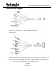
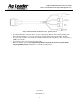
2202 South Riverside Drive, Ames, IA 50010 Phone: 515-232-5363 Internet: http://www.agleader.com Technician Cable Diagrams: Figure 2: Mobile Technician Cable – p/n-201-0176-01 • • Connect the power connection to the power cable. Connect the Setup Port to a COM port of a PC. Use the Base Configuration Tool to communicate with the GPS receiver. Connect the Freewave/Satel Modem port to a PC to communicate with the internal Radio using the AF Link program.
2202 South Riverside Drive, Ames, IA 50010 Phone: 515-232-5363 Internet: http://www.agleader.com Figure 4: External Radio Technician Cable - p/n-201-0221-01 • • • • The External Radio Technician cable is used to communicate with the Tower Radio and Repeater. Benco Kit p/n-212303 is necessary to change the communication rate from RS-232 to RS-422. The Benco kit should be connected to Port 2 (labeled RS-232 / RS-422) which is then connected to a COM port of the PC.
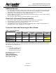
2202 South Riverside Drive, Ames, IA 50010 Phone: 515-232-5363 Internet: http://www.agleader.com Base Station Configuration Tool: Manually entering a known lon/lat position Pre-requisites: Base Configuration Tool should be installed on PC and A5 Base should be upgraded to latest Base Station firmware. A5 Base must be at version V1.27 or higher. Procedure: 1. 2. 3. 4. Install Base Configuration Tool to your PC. Place Base Station in its final desired position.
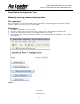
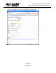
2202 South Riverside Drive, Ames, IA 50010 Phone: 515-232-5363 Internet: http://www.agleader.com 5. In the address bar of web page, remove “autofarm.html” so that you see: “http://localhost:8080/” the page changes to appear as shown in Figure 3.
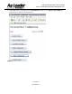
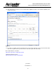
2202 South Riverside Drive, Ames, IA 50010 Phone: 515-232-5363 Internet: http://www.agleader.com 6. Select proper Com port and click on “Base Location Config” tab. Following screen will appear. Figure 7 7. Refresh the web page by hitting F5 key on key board, till base station calculates position and shows it as follow. The line “SPS average for 28 sec” indicates that base has averaged position for 28 seconds. This time will increase every time you refresh web page. 8.
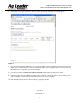
2202 South Riverside Drive, Ames, IA 50010 Phone: 515-232-5363 Internet: http://www.agleader.com 11. Select “Use Average Position” as Type of Height Measurement as follows. Name this location for your reference say “MyBaseLocation”. Do not change Coordinate Accuracy.
2202 South Riverside Drive, Ames, IA 50010 Phone: 515-232-5363 Internet: http://www.agleader.com 12. Click ‘Add’ button to get this screen. See that location “MyBaseLocation” is stored in Base database and is marked as Active. Figure 9 13. Procedure is complete, disconnect the PC. Now you can power off the base, disconnect technician cable and connect regular cable if you want. Power on the base again and start using it. Base Station distance calculator: http://www.csgnetwork.com/gpsdistcalc.
2202 South Riverside Drive, Ames, IA 50010 Phone: 515-232-5363 Internet: http://www.agleader.com AF Link Programming Utility: Installation: The software package includes 2 files: • AFLinkPgmUtil.exe • AFLink Programming Utility User Manual The User Manual listed here above is this user manual. Description of the Software: When starting up the software, you will see a window as shown on Figure 10.
2202 South Riverside Drive, Ames, IA 50010 Phone: 515-232-5363 Internet: http://www.agleader.com Figure 12 - About Window To start programming the radio the user presses the Detect Radio button (or Alt+D), the software initiates the detection logic. The software will then prompt the user to make sure that the radio that needs to be programmed is in programming mode. Figure 13 here below shows the message displayed by the software. Press cancel button to cancel the task. Press ‘Ok’ button to do detection.
2202 South Riverside Drive, Ames, IA 50010 Phone: 515-232-5363 Internet: http://www.agleader.com Figure 14 - Satel radio detected One can see that the title in the frame under the Detect Radio button is showing the radio type (Satelline – 3AS in this case), Firmware version, Hw information. At the bottom of the screen, one can see 2 boxes, the left one shows the internal modem type and the right box shows the port setting for the detected radio.
2202 South Riverside Drive, Ames, IA 50010 Phone: 515-232-5363 Internet: http://www.agleader.com Figure 15 - Satel AFLink usage choices In terms radio usage, Figure 15 shows the possible options which are: • Tractor / Mobile Base Station – This setting is to be used if the AFLink is going to be put on a Roof Module or if it will be connected to a portable Base Station. In either of these cases, the programming of the radio is identical. • Repeater – The AFLink is going to be connected to a Repeater.
2202 South Riverside Drive, Ames, IA 50010 Phone: 515-232-5363 Internet: http://www.agleader.com Figure 16 - AFLink Pgm Util screen for intermediate and advanced users The output power choices depend on the type of radio as shown in Table 2. Satelline – 3AS 10 mW 20 mW 50 mW 100 mW 200 mW 500 mW 1000 mW Satelline – 3AS EPIC 1W 2W 5W 10 W Table 2 - Satel radio output power choices Figure 17 shows an example of the power choices for a 3AS radio.
2202 South Riverside Drive, Ames, IA 50010 Phone: 515-232-5363 Internet: http://www.agleader.com Figure 17 - AFLink Pgm Util output power selection Finally, when all programming options are selected, the user can press the Program Radio button to start programming the radio. Note that the button is only enabled if all fields are correctly filled. If any of the fields has an invalid entry, the Program Radio button will be disabled.
2202 South Riverside Drive, Ames, IA 50010 Phone: 515-232-5363 Internet: http://www.agleader.com AFLink with FreeWave radio: When programming an AFLink radio with a FreeWave radio the programming button on the programming cable must be pushed in. FreeWave radios enter the programming mode when the programming switch is being pushed-in and pushed out (Freewave uses edge detection. So, user needs to switch the programming button on and off).
2202 South Riverside Drive, Ames, IA 50010 Phone: 515-232-5363 Internet: http://www.agleader.com Figure 20 – Freewave radio detected The desired radio channel the user gets to choose should be a value between 0 and 3824. Note that invalid entries (smaller than 0 or larger than 3824) will be set to 0 or 3824 (respectively). When no channel is entered, the latest valid channel is used. NOTE: The Frequency Key on the radio is computed from the channel number.
2202 South Riverside Drive, Ames, IA 50010 Phone: 515-232-5363 Internet: http://www.agleader.com Figure 22 - AFLink Freewave usage choice If the firmware version is 2.64, user can set mode to be “Legacy”, or “Fast Roaming” mode as shown in Figure 23. In Legacy mode, Tractor, Repeaters only accept the packages sent from the base station with the same network id. In “Fast Roaming” mode, Tractor and repeaters can accept the packages sent from the base stations out of the network.
2202 South Riverside Drive, Ames, IA 50010 Phone: 515-232-5363 Internet: http://www.agleader.com If the firmware is not 2.64, only “legacy” mode is supported. Firmware update button will be shown if the firmware doesn’t support “fast roaming” mode. User can press this button to update firmware as shown in Figure 15 (some old hardware will not support new firmware). . Figure 24 - AFLink Freewave firmware update for version older than 2.
2202 South Riverside Drive, Ames, IA 50010 Phone: 515-232-5363 Internet: http://www.agleader.com As shown on Error! Reference source not found.6, the 2 countries currently supported by the AFLink with Freewave radios are: • The United States of America • Australia When all boxes contain valid entries, the software enables the Program Radio button. The user can then click the button in order to load the current settings to the radio.
02 South Riverside Drive, Ames, IA 50010 Phone: 515-232-5363 Internet: http://www.agleader.com Advanced User Features: The advanced user features will be shortly introduced here. A full description is out of the scope of this document. For more details about the advanced features, contact AutoFarm. When the advanced features are enabled, the users can right-click anywhere within the software window and get the pop-up menu shown on Figure 27.