Base Station Hardware Manual PN: 602-0024-02-C
Legal Disclaimer Note: Read and follow ALL instructions in this manual carefully before installing or operating the AutoSteer system. Note: Take careful note of the safety information in the Safety Information section and throughout this manual. The manufacturer disclaims any liability for damage or injury that results from failure to follow the instructions and warnings set forth herein. Technical Support Contact your dealer for technical support. Base Station Hardware Manual Copyright © 2010.
Table of Contents Chapter 1 Introduction ................................................................................................... 3 RTK and Base Station Basics . . . . . . . . . . . . . . . . . . . . . . . . . . . . . . . . . . . . . . . . . . . . . . . . . . 3 Repeatability . . . . . . . . . . . . . . . . . . . . . . . . . . . . . . . . . . . . . . . . . . . . . . . . . . . . . . . . . . . . . 4 Accurate Latitude and Longitude Positions. . . . . . . . . . . . . . . . . . . . . . . . . . . . . .
Table of Contents Radio Modem Kit Components . . . . . . . . . . . . . . . . . . . . . . . . . . . . . . . . . . . . . . . . . . . . . . 42 Base Station Receiver Faceplate LEDs and Connectors . . . . . . . . . . . . . . . . . . . . . . . . . . . 42 Hardware Installation . . . . . . . . . . . . . . . . . . . . . . . . . . . . . . . . . . . . . . . . . . . . . . . . . . . . . . . . 43 Mount GPS Antenna . . . . . . . . . . . . . . . . . . . . . . . . . . . . . . . . . . . . . . . . . . . . . . . . . . . . . .
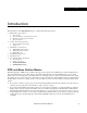
1 Introduction The information for this Introduction chapter is contained in the following sections: • • • • • • RTK and Base Station Basics • Repeatability • Accurate Latitude and Longitude Positions • Maximizing Positioning Performance • Repeater Options A5 Base Station Configurations • A5 Steer Mobile Base Station • A5 Repeater AFLink Base Configurations • AFLink Mobile Base Station • AFLink Fixed Base Station • AFLink Repeater AFLink Radio Regulations FCC Regulations Important Regulatory Information
Repeatability Repeatability Repeatability is the ability to return your vehicle to a previously established field and repeat or continue a saved job (Autosteer over the same guidance paths), whether it is the next day or the next season. For example, if you want to install drip tape, not only do you want to put it in the ground straight, you want the ability to return to that field and make beds directly over the top of the drip tape. The same is true for cultivating or harvesting.
Accurate Latitude and Longitude Positions advantage of this method is that it provides a large RTK coverage area without the need to move the Base Station components once they have been installed. Accurate Latitude and Longitude Positions Mapping functions of the User Display and/or 3rd party software for boundary creation or variable rate applications require an accurate latitude and longitude position for the vehicle.
Accurate Latitude and Longitude Positions • The ST LED will continue to blink once per second until it has averaged 24 hours of position data. Note that if position data drops below an acceptable range, the data will not be included in the average and the overall time will be increased proportionally. 4.
Maximizing Positioning Performance Using a Known Position for Accurate Latitude and Longitude A known Base Station location can also be entered manually by your dealer using the Base Station Configuration tool, the proper service cables, and a laptop. This option should be used only if the exact position is known. If an incorrect position is entered into the Base Station, the latitude and longitudes of the vehicle uses for display functions and 3rd party software will be shifted.
Repeater Options Repeater Options An RTK system works only when the radio link between the Base Station and rovers are line of site. The radio waves transmitted from the Base Station can be blocked by obstacles such as trees, hills, buildings, etc. In order to get a radio signal around these obstacles, a repeater can be used to receive and then retransmit an RTK signal. The repeater is placed at a point where it is in view of both the Base Station and the mobile receiver.
A5 Base Station Configurations A5 Base Station Configurations The RTK Base Station is available in the configurations described in the this section. Additionally, a repeater to route signals around obstacles is available. A5 Steer Mobile Base Station The A5 Steer Mobile Base Station is designed for use with the AutoSteer module. • Part number: 130-0033-01 or 4100651-1 (AL) A5 Repeater The A5 Repeater is an external radio modem and antenna used to retransmit RTK signals around obstacles.
AFLink Repeater AFLink Repeater This is an external AFLink radio modem and antenna used to retransmit RTK signals around obstacles. This version will work with AFLink Base Station models. The AFLink Repeater must match the frequency of the Base Station and rover. AFLink Radio Regulations The standard A5 Base Stations do not require a license to operate as they operate on the public 900MHz frequency. The AFLink radios broadcast on a regulated frequency.
Important Regulatory Information You must be familiar with Part 90 of FCC Rules before you operate your device. The operation instructions in this manual conform to Part 90, but do not cover all items in Part 90. Form 600 instructions only 006001 Main Form 600 only 006002 Form 600 schedules only 006003 8 FCC Regulations Overall, Part 90 states that: • • • • • • • You must have a valid license before you use the device.
Restricciones de uso Novariant se reserva el derecho de cambiar las especificaciones técnicas o funciones de sus productos, de cesar en la producción o soporte de cualquiera de sus productos sin previo aviso por escrito e insta a sus clientes a asegurar, que la información a su disposición es válida. El software y programas de Novariant se entregan tal cual. El fabricante no ofrece ningún tipo de garantía de venta o relacionadas con la aplicabilidad de una cierta aplicación.
WICHTIGER HINWEIS • Para prevenir el daño tanto del radio módem como de cualquier terminal debe siempre estar apagado (OFF) antes de conectar o desconectar el cable de conexión de serie. El usuario debería asegurarse de que los diferentes aparatos utilizados tengan el mismo potencial de tierra. Antes de conectar cualquier cable de potencia el voltaje del suministro debe ser comprobado.
BETRIEBSERLAUBNIS HINWEISE ZU GEWÄHRLEISTUNG UND SICHERHEIT Bitte lesen Sie folgende Sicherheitshinweise aufmerksam durch, bevor Sie das Produkt einsetzen: Die Garantie geht verloren, wenn das Produkt in einer anderen Weise als in diesem Handbuch beschrieben eingesetzt wird oder wenn das Gehäuse des Funkmodems geöffnet oder gewaltsam beschädigt wurde.
2 A5 Steer Base Station This A5 Steer Base Station chapter contains information in the following sections: • • • • • Determining a Location for the Mobile Base Station Hardware Components • Back and Bottom Panel Hardware and Connectors • Faceplate LEDs Hardware Setup Providing Power Breaking Down the Base Station Determining a Location for the Mobile Base Station The Base Station GPS Antenna receives position measurements from the GPS satellites.
Hardware Components Note: To resume using your AutoSteer system on the rows that are saved with a previous job, you must set up the Base Station GPS Antenna in the exact location as when you originally worked in that field. This is true whether it is the next day or the next season. We strongly suggest creating a semi-permanent mounting for each field site so the Base Station can be precisely relocated for future use. See the Repeatability on page 4 for more information.
Back and Bottom Panel Hardware and Connectors Part Description Part Number 3. Female Quick-Release Coupler (To be attached to the Base Station) 311-0005-01 4. Male Quick-Release Coupler (To be attached to the Tripod mount) 311-0003-01 5. Mobile Base Station (Base station has the following ports and parts): 200-0196-04 6.
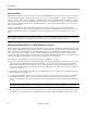
Faceplate LEDs Figure 2-4 Table 2-2 GPS Receiver Faceplate LED Display Function Definition LED Definition Function RX Receive LED usually is not lit. However, it will occasionally flash indicating a data packet is being sent from the internal or external radio modem to the Base Station GPS Receiver. TX Transmit Blinks as data is transmitted from the Base Station GPS Receiver to the internal or external radio modem. This can also be steady/green if the data flow is continuous.
Hardware Setup Hardware Setup 1. Set up the Tripod so the mounting plate is level. 2. Press the button on the Female Quick-Release Coupler to separate it from the Male Quick-Release Coupler. Push the Release Button. Note: This step can be skipped if the Male Quick-Release Coupler is stored attached to the Tripod.
Hardware Setup 3. Attach the Female Quick-Release Coupler to the bottom of the Base Station. 4. Place the Washer on top of the Tripod base. Note: This step can be skipped if the Male Quick-Release Coupler is stored attached to the Tripod.
Hardware Setup 5. Attach the Male Quick-Release Coupler to the Tripod. Note: This step can be skipped if the Male Quick-Release Coupler is stored attached to the Tripod. 6. Mount the Base Station on top of the Tripod by connecting the Female Quick-Release Coupler to the Male Quick-Release Coupler.
Providing Power 7. Rotate the Radio Modem Antenna into an upright position so it fits through the slot on the ground plane of the GPS Antenna. Verify that the connector is tight. Note: The antenna should already be connected into the DLINK port. Radio Modem Antenna Note: Once the two Quick-Release Couplers are attached to their respective components, keep them intact and press the Female Quick-Release Coupler button to move the Base Station on and off the Tripod. Providing Power 1.
Providing Power 2. Connect a fully charged 12-volt, deep-cycle marine battery to the power cable using the alligator clips after all the other connections have been completed and the Base Station is mounted in the proper position. Note: Since the Base Station does not have a power switch, the connect/disconnect battery cable serves as the switch. Note: Always start field operations with a fresh, fully charged battery.
Breaking Down the Base Station Breaking Down the Base Station 1. Disconnect the Base Station from the power supply. 2. Unplug the12-Volt Battery Power Supply Cable from the Base Station. 3. Fold the Radio Modem Antenna so it wraps around the Base Station.
Breaking Down the Base Station 4. Press the Female Quick-Release Coupler button and remove the Base Station from the Tripod. 5. Remove the Female Quick-Release Coupler from the Base Station. 6. Collapse the Tripod. The Flat Washer and Male Quick-Release Coupler can stay attached to the Tripod.
Breaking Down the Base Station 7. Store and transport the A5 Steer Base Station equipment in its case.
3 AFLink Mobile Base Station This AFLink Mobile Base Station chapter contains information in the following sections: • • • • • • • Determine a Mobile Location Base Station Components Radio Modem Kit Components • Bottom Panel Hardware and Connectors • Faceplate LEDs Connecting the Components Providing Power Breaking Down the Base Station AFLink Software Configuration Hardware Installation Manual 27
Determine a Mobile Location Determine a Mobile Location The Base Station GPS Antenna receives position measurements from the GPS satellites. The Base Station calculates the position error and transmits the correction data to the vehicle via an AFLink radio modem link. This radio modem link requires a line-of-sight between the vehicle and the Base Station. The higher the elevation the Radio Modem Antenna is positioned in, the more easily a vehicle can receive a clear signal.
Base Station Components Figure 3-2 AFLink Mobile Base Station Components Table 3-1 AFLink Mobile Base Station Component Definitions and Part Numbers Part Description Part Number 1. Tripod 500-0163-01 2. Radio Modem Antenna Bracket Assembly (Includes bracket, Radio Modem Antenna Cable, and cable fasteners) 202-0148-01 3. Female Quick-Release Coupler (To be attached to the Base Station) 311-0005-01 4. Male Quick-Release Coupler (To be attached to the Tripod mount) 311-0003-01 5.
Radio Modem Kit Components Radio Modem Kit Components The Radio Modem Kit components are shown in Figure 3-3. Figure 3-3 AFLink Steer Base Radio Modem Components Bottom Panel Hardware and Connectors The bottom panel hardware is shown in Figure 3-4.
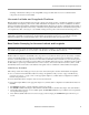
Faceplate LEDs Faceplate LEDs The LED display indicates system status. The specific symbols and meanings are listed in Table 3-2 (from bottom left to right). Figure 3-5 AFLink Mobile Base Station Faceplate Table 3-2 LED Display Function Definition Sym Meaning Display RX Receive (reserved) Reserved for future use. TX Transmit (data out to the vehicle) Blinks as data is transmitted. This can also be steady/green if the data flow is continuous.
Connecting the Components Connecting the Components 1. Set up the Tripod so the top mounting plate is level. 2. Press the Female Quick-Release Coupler button to separate it from the Male Quick-Release Coupler. Note: This step can be skipped if the Male Quick-Release Coupler is stored attached to the Tripod.
Connecting the Components 3. Attach the Female Quick-Release Coupler to the bottom of the Base Station. 4. Assemble the Radio Modem Antenna bracket as shown. Attach the Radio Modem Antenna to the bracket and then attached to one end and the radio modem coax cable to the antenna. Secure the radio modem coax cable to the bracket using the plastic clips. Note: This assemble can be kept together when disassembling and storage. 5.
Providing Power 8. Attach the radio modem mounting bracket to one of the Tripod legs so that the radio modem is mounted with the label upright. 9. Connect the Radio Modem Antenna Cable to the radio modem. Note: Once the two Quick-Release Couplers are attached to their respective components, keep them intact and press the Female Quick-Release Coupler button to move the Base Station on and off the Tripod. Providing Power 1. Fasten the power cable to the bottom of the Base Station.
Providing Power 2. Connect a fully charged 12-volt, deep-cycle marine battery to the Base Station power cable using the alligator clips after all the other connections have been completed and the Base Station is mounted in the proper position. Note: Since the Base Station does not have a power switch, the connect/disconnect battery cable serves as the switch. Note: Always start field operations with a fresh, fully charged battery.
Breaking Down the Base Station Breaking Down the Base Station 1. Disconnect the Base Station from the power supply. 2. Unplug the power cable from the Base Station.
Breaking Down the Base Station 3. Fold the Radio Modem Antenna so it wraps around the Base Station. Press the Female Quick-Release Coupler button and remove the Base Station from the Tripod. 4. Remove the Female Quick-Release Coupler from the Base Station. 5. Collapse the Tripod. The Washer and Male Quick-Release Coupler can stay attached to the Tripod.
AFLink Software Configuration 6. Store and transport the A5 Steer Base Station equipment in its case. AFLink Software Configuration The Base Station AFLink radio modem must have its frequency set to the one that matches the owner’s license. The AutoSteer system dealer should be able to set this frequency using the AFLink Programming Utility.
4 AFLink Fixed Base Station This AFLink Fixed Base Station chapter contains information in the following sections: • • • Determining a Location for the AFLink Fixed Base Station • Hardware Component Spacing AFLink Fixed Base Station Hardware Components • Base Station Kit • Radio Modem Kit Components • Base Station Receiver Faceplate LEDs and Connectors Hardware Installation • Mount GPS Antenna • Mount Radio Modem Antenna • Installing the AFLink Radio Modem • Connecting the GPS and Radio Modem Antennas •
Hardware Component Spacing Note: The AFLink Fixed Base Station uses an AFLink radio to transmit the radio modem information. The AFLink radio that is used must be matched to follow the licensing laws for the region where it is installed. Before using an AFLink radio, verify that the proper frequency has been ordered and that it matches the license held by the owner. Note: The Base Station Receiver and AFLink radio modem are protected by a weatherproof enclosure supplied with the kit.
AFLink Fixed Base Station Hardware Components AFLink Fixed Base Station Hardware Components The AFLink Fixed Base Station comes in two hardware kits: (1) a Base Station Kit, and (2) An AFLink Radio Modem Kit. The components in these kits are described in the sections that follow. Base Station Kit The AFLink Fixed Base Station components are shown in Figure 4-2.
Radio Modem Kit Components Radio Modem Kit Components The Radio Modem Kit components are shown in Figure 4-3. Figure 4-3 Radio Modem Kit Components Base Station Receiver Faceplate LEDs and Connectors The faceplate of the Base Station contains LEDs that indicate system status. Table 4-1 provides details on the LEDs. The faceplate also contains the following port (see Figure 4-4): • GPS Antenna Port [B] Note: The Base Station Receiver is mounted inside the enclosure, behind a mounting plate.
Hardware Installation Table 4-1 LED Display Function Definition LED Definition Function RX Receive LED usually is not lit. However, it will occasionally flash indicating a data packet is being sent from the internal or external radio modem to the Base Station GPS Receiver. TX Transmit Blinks as data is transmitted from the Base Station GPS Receiver to the internal or external radio modem. This can also be steady/green if the data flow is continuous.
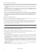
Mount GPS Antenna Note: The Base Station GPS Antenna mounting position must be in a sturdy, unmovable place. This can be on top of a sturdy building or on a solid pole near the ground. We do not recommend mounting this antenna on a tower or grain leg as they generally are not sturdy enough to prevent movement. Note: The GPS Antenna must have a clear view of the sky.
Mount GPS Antenna Figure 4-6 Incorrect Base Station GPS Antenna Positioning 2. Mount the GPS Antenna. 3. Attach the right angle connector of the GPS Antenna Cable to the GPS Antenna.
Mount Radio Modem Antenna 4. Route the GPS Antenna Cable from the GPS Antenna to the Base Station Receiver. Secure the cable all along the route to keep it from being damaged. Mount Radio Modem Antenna 1. Assemble the Radio Modem Antenna bracket to the Radio Modem Antenna. Connect the Radio Modem Antenna to the Prism pole. 2.
Mount Radio Modem Antenna Note: The Radio Modem Antenna can move slightly after being installed without having any effect on the performance of the RTK system. Mounting this antenna on top of a radio tower or grain leg is acceptable to provide maximum range. Figure 4-7 Correct Base Station Radio Modem Antenna Positioning Figure 4-8 Incorrect Base Station Radio Modem Antenna Positioning 3. Mount the Radio Modem Antenna.
Mount the Base Station Enclosure 4. Attach the connector of the Radio Modem Antenna Cable to the Radio Modem Antenna. 5. Route the Radio Modem Antenna Cable from the Radio Modem Antenna to the Base Station Receiver. Secure the cable all along the route to keep it from being damaged. Mount the Base Station Enclosure 1. Install the Base Station enclosure firmly against a wall or other sturdy structure that is easily accessible and near a power source.
Installing the AFLink Radio Modem 3. Install the earth ground per the local regulations that specify lightning protection grounding. Note: Picture shows other connections already connected. Installing the AFLink Radio Modem 1. Loosen the 2 - Phillips screws on clamps holding enclosure door closed. The screws are located on the right side of the enclosure. Note: The screws do not need to be completely removed. They can be loosened until the clamp can be slid from over the lip holding the door closed.
Installing the AFLink Radio Modem 2. Use the enclosed key to open the lock on the enclosure. Pull the door open to access the interior. 3. The Base Station Receiver is accessible by loosening the two screws that hold the internal panel closed. Note: It is not necessary to remove these screws during installation. This is shown to demonstrate how to service the Receiver.
Installing the AFLink Radio Modem 4. To service the Base Station Receiver, four bolts need to be removed so the Receiver can be removed from the enclosure. Note: It is not necessary to remove these bolts during installation. This is brought up for reference in case the Receiver needs to be serviced in the future. 5. The AFLink radio modem is mounted to the mounting plate. Remove the four screws in the mounting plate.
Installing the AFLink Radio Modem 6. Install AFLink radio modem and reattach using screws that were just removed. 7. Connect the Radio Modem Antenna lead from the enclosure to the left antenna connector on the AFLink radio modem. 8. Connect the radio modem power/data cable from the Base Station Receiver to the power/data port of the AFLink radio modem.
Connecting the GPS and Radio Modem Antennas 9. The AFLink radio modem has now been properly installed. Close the enclosure door, lock with the enclosed key, and clamp sides of enclosure with clamps to ensure the box is weatherproof. Note: Keep the key in a secure place. Connecting the GPS and Radio Modem Antennas 1. Attach the GPS Antenna cable to the GPS (blue) connector on the bottom of the enclosure. Verify that the connector adapter is present. Hand tighten only.
Installing and Powering ON the Base Station 2. Attach the Radio Modem Antenna Cable to the radio modem (red) connector on the bottom of the enclosure. Hand tighten only. Note: Inverted coax cable connections immediately damage the GPS Antenna when the Base Station is turned on. Verify the cable colors match the colors on the identification label. Installing and Powering ON the Base Station 1. Attach the power supply cable to the connector on the bottom of the enclosure. 2.
Installing and Powering ON the Base Station 3. After attaching all connectors to supply power to the Base Station, turn the power inverter’s power switch to the ON position. Note: Verify that all antennas and antenna cables have been installed and are properly mounted before supplying power to the Base Station enclosure. Failure to do this may cause damage to the radio components. Note: The Base Station begins transmitting RTK correction signals within a minute of powering up.
Installing and Powering ON the Base Station 56 AutoSteer System
5 A5 and AFLink Repeaters This A5 and AFLink Repeaters chapter contains information in the following sections: • • • • • • • • • Introduction to A5 and AFLink Repeaters • Repeater Concepts Determining a Location for the Repeater Using a Repeater • Daisy Chaining • Multiple Repeater Setup Incorrect Repeater Usage Hardware Components • A5 Repeater Components • AFLink Repeater Components Assembling the Repeater Mounting Options • Tripod Mounting • Using a Pole Mount • Mounting in a Permanent Location Provid
Introduction to A5 and AFLink Repeaters Introduction to A5 and AFLink Repeaters There are two versions of the Repeater. They are the A5 Repeater and the AFLink Repeater. The A5 Repeater works with all the Base Stations versions that use the 900 MHz radio modem. The AFLink Repeater works with all the Base Station versions that use the 400 MHz AFLink radio modems.
Determining a Location for the Repeater Determining a Location for the Repeater The repeater must be placed in a location that is within line-of-sight of both the Base Station and the vehicle. The exact location of a repeater does not affect job repeatability. The Base Station’s GPS Antenna is always the reference position for repeatability. Figure 6-1 shows a common repeater-Base Station setup in a typical field. Alternate configurations are described later in this chapter.
Using a Repeater Using a Repeater There are three main features and configuration options to keep in mind when using a repeater. Before ordering a repeater discuss these needs with your AutoSteer dealer and verify they will work in your situation. The three options are: • • Daisy Chaining Multiple-Repeater Setup Daisy Chaining In some situations, one Repeater may not provide adequate coverage for the area around a Base Station.
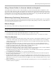
Daisy Chaining Figure 6-2 shows an example of repeaters being set up in a daisy chain configuration. • • • • • • The shaded area labeled (6) no coverage by a RTK signal (or are outside the 6 mile (9.7 km) range of the Base Station). The shaded area labeled (5) indicate coverage by the Base Station transmitter (B) only. The shaded area labeled (4) indicate coverage by the Base Station and Repeater 1 (R1). The shaded area labeled (3) indicate coverage by the Base Station, Repeater 1, and Repeater 2 (R2).
Multiple Repeater Setup Multiple Repeater Setup Multiple repeaters can also be set up in various locations around the Base Station to repeat signals from the same Base Station. In this scenario both repeaters can receive correction signals from the Base Station, but they cannot communicate with each other. In this case, an obstacle may block part of the path of the Base Station signal in more than one direction.
Incorrect Repeater Usage Incorrect Repeater Usage The repeater cannot be used to extend the Base Station sub-inch accuracy range in the manner shown in Figure 6-4. In this example the vehicle is being driven inside the coverage area of the repeater. However the vehicle is outside the Base Station’s original 6 mile (9.7 km) effective range. The vehicle may not achieve sub-inch accuracy in this area.
Hardware Components Hardware Components This section describes the hardware components that are shipped with each version of Repeater. An optional Tripod (500-0163-01) for installing the repeater in portable applications and a 4 foot (1.2 Meter) pole section (500-0003-01) or 12 foot (3.6 meter) pole kit (200-0315-01) for installing the repeater in permanent installations are also available and can be ordered separately to facilitate optional mounting situations.
AFLink Repeater Components Part Description Part Number 3. Radio Modem Bracket Assembly 200-0334-01 4. 6 dBi Antenna 500-0006-01 5. Repeater Modem Antenna Cable 201-0246-01 AFLink Repeater Components The AFLink Repeater components are shown in Figure 5-6and defined in Table 5-2. Figure 5-6 AFLink Repeater Components Table 5-2 Repeater Component Definitions and Part Numbers Part Description Part Number 1. Repeater Power Cable 201-0205-01 2.
Assembling the Repeater Part Description Part Number 3. Repeater Bracket Assembly 200-0334-01 4. Antenna 500-0006-01 5. AFLink Radio 201-0246-01 Assembling the Repeater 1. Assemble the Radio Modem Bracket Assembly as shown in the diagram. The U-bolts and Washer are to be used later if necessary. The final assembly is shown on the right. 2. Attach the A5 Repeater Radio Modem to the Radio Modem Bracket Assembly using the four screws provided. 3.
Mounting Options Mounting Options The repeater can be mounted on a Tripod, pole or other permanent location as described in the following sections. Tripod Mounting If the optional Tripod (500-0163-01) has been ordered use the following procedure to set up the Repeater. 1. Set up the Tripod so the mounting plate is level. 2. Place the Washer on top of the Tripod base. 3. Firmly attach the repeater to the Tripod with the Tripod nut. 4.
Using a Pole Mount Using a Pole Mount If the optional 4 foot (1.2 Meter) pole section (500-0003-01) or 12 foot (3.6 meter) pole kit (200-0315-01) has been ordered, use the following instructions to mount the Repeater. 1. Set mounting pole in the desired location. 2. Screw repeater assembly to the top of the mounting pole.
Mounting in a Permanent Location 3. Verify that the antenna is perpendicular to the ground after it is set up. Mounting in a Permanent Location 1. Mount mounting bracket to permanent site. 2. Attach the repeater assembly to permanent mounting bracket using U-bolts. 3. Verify that the antenna is perpendicular to the surface of the Earth after it is set up. Providing Power 1.
Breaking Down the Repeater Note: Always start field operations with a fresh, fully charged battery. The battery should not be charged to more than 14 volts or enabled to go to less than 12.0 volts. Operating the repeater at less than 12.0 volts can cause erratic data transfer problems. Note: Do not leave the power cable connected to the repeater overnight, as the resulting reduced battery power can significantly decrease the effective range of the signal.