Version 2.
Table of Contents Introduction...............................................................................................................................................................1 Legal Notices.................................................................................................................................................1 About the EZ−Guide 250 System..................................................................................................................
Table of Contents Advanced Mode Additional Information..............................................................................................................46 Views...........................................................................................................................................................46 Panning.........................................................................................................................................................46 Night Mode.........
Table of Contents Obtaining Information from the Lightbar Warning Messages.......................................................................................................................................79 Troubleshooting...........................................................................................................................................
Introduction Legal Notices (c) 2007, Trimble Navigation Limited. All rights reserved. Trimble, AgGPS, EZ−Guide, and EZ−Steer are trademarks of Trimble Navigation Limited, registered in the United States and in other countries. Autopilot, Autoseed, FreeForm, OnPath, and SiteNet are trademarks of Trimble Navigation Limited. All other trademarks are the property of their respective owners.
• multiple field patterns for different field layouts Related Information Sources of related information include the following: • Help − the lightbar has built−in, context−sensitive help that lets you quickly find the information you need. • Quick reference card − the quick reference card describes the most common features of the lightbar. Technical Support If you have a problem and cannot find the information you need in the product documentation, contact your local reseller.
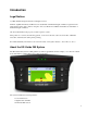
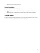
About the Lightbar What's in the EZ−Guide 250 Box The standard components of the EZ−Guide 250 system are shown below. ITEM DESCRIPTION 1 EZ−Guide 250 documentation CD 2 Quick Reference Card 3 RAM mount 4 Antenna mount plate 5 Power cable (P/N 65168) 6 EZ−Guide 250 lightbar 7 Patch antenna When you unpack the box, inspect all contents for visible damage, such as scratches or dents. If any components appear damaged, notify the shipping carrier.
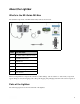
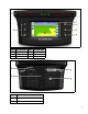
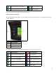
ITEM 1 2 3 DESCRIPTION Action icons OK button Up button ITEM 4 5 6 DESCRIPTION Down button Function buttons LEDs ITEM DESCRIPTION 1 12−pin Deutsch power/data connector 2 Antenna port 4
3 RAM mount fixture 4 USB port How the Buttons Work On the front of the lightbar, there are six buttons. The buttons on the left and right sides of the lightbar work in different ways. Action buttons (on the right of the screen) On the main guidance screen: • Press • Press or to scroll through the action icons. to select the highlighted icon.
Increase value / up to next option Proceed to next screen Decrease value / down to next option Accept settings In setup screens, the icons match the buttons beside them. Function buttons (on the left) Beside each function button, there is an icon. When you press the function button, you select the feature that is shown on the icon.
Getting help The EZ−Guide 250 lightbar has built−in help that explains how to use the current screen. To access the help, press the function button: Optional Accessories • Ag15 antenna upgrade (P/N 92010−00) • All−port cable (P/N 64045) • Suction cup (P/N 44922) Upgrades The EZ−Guide 250 lightbar guidance system can be connected to the EZ−Steer® 500 assisted steering system. Fuse Information The EZ−Guide 250 lightbar has a 10 A glass cartridge fuse located in the cigarette lighter plug.
• Outputting simulated radar to send speed to another agricultural device, such as a yield monitor or a variable rate controller. • Outputting NMEA messages to an external device. To add a serial port to the standard lightbar cable: 1. Do one of the following: ♦ Order the EZ−Guide 250 all−port cable (P/N 64045). ♦ Order the serial port add−on cable (P/N 63076). 2. Identify P2 on the power cable (P/N 65168). It is the black 12−pin Deutsch connector. 3.
Installation Step 1: Installing the Antenna Note: To minimize any interference to the GPS signal, make sure that the GPS antenna is at least 2 m (6 ft) from any other antenna (including a radio antenna). You may experience interference if you operate the vehicle within 100 m (300 ft) of any power line, radar dish, or cell phone tower. Installing the Patch Antenna Find the mounting location for the antenna at the front of the vehicle roof, centered from left to right. 1.
ITEM DESCRIPTION 1 EZ−Guide 250 lightbar 2 Patch antenna 3 12−pin Deutsch power cable (P/N 65168) 4 To power (cigarette lighter) 1. Connect the power/data cable (P/N 65168) to the power port on the back of the lightbar. 2. Connect the other end of the power/data cable to the vehicle cigarette lighter. 3. Connect the antenna cable to the antenna port. Caution: If you are using the EZ−Seer system, do not disconnect or connect any cables to the system while the lightbar is running.
You can leave the lightbar connected to the cable when it is turned off. It may draw a small amount of current, but it will not drain the vehicle battery. If the lightbar loses power but then receives power again within 15 seconds, for example when cranking the vehicle starter, the lightbar will turn on automatically. Connecting a Coverage Switch To install the coverage switch, refer to the instructions provided with the coverage switch. Enabling the switch on the lightbar From the main guidance screen: 1.
Getting Started Quick Start Wizard When you turn on the lightbar the Welcome to EZ−Guide screen appears automatically: Press . The Quick Start Wizard appears. The wizard has several setup screens that enable you to configure important settings before you begin driving. During the Quick Start Wizard, you can press the function button to exit at any point. The system uses any settings you have entered; for any settings that you have not yet entered, the system uses the settings from last time.
To adjust a setting: 1. Press 2. Press or to select the correct value. to enter the selection and proceed. You can select whether or not the Quick Start Wizard appears next time you turn on the lightbar. If you choose to hide the wizard at startup, the lightbar skips the wizard and starts on the main guidance screen. To alter these settings after startup, run the Quick Start Wizard from Configuration / Quick Start Wizard. Once you complete the Quick Start Wizard, the main guidance screen appears.
Status Indicators On the main guidance screen, the lightbar has two status indicators.
By default, the view switches from plan view to perspective view when you enter the field. You can change the view mode in Advanced mode. User Modes The EZ−Guide 250 lightbar guidance system has two user modes: MODE DESCRIPTION Easy Limited to accessing the most simple features. Fewer action icons are available. Simplified driver options (for example, creating a guidance line is easier). Advanced The user can access all of the settings.
Changing the LED Brightness To adjust the brightness of the LEDs on the lightbar, select Configuration / LED Brightness. • In bright sunlight, increase the brightness to make the LEDs more obvious. • In darker conditions, for example driving at dusk, you can lower the brightness settings so the LEDs are less intense.
Easy Mode Guidance Introduction to Guidance The EZ−Guide 250 lightbar uses onscreen lines, either straight or curved, to guide you. These are called the guidance lines. The most simple form of guidance line is a straight AB Line. To create an AB Line, you define a start point (the A point) and an end point (the B point). Once you define the A and B points, a straight line is drawn between them. This is your master line.
ITEM DESCRIPTION The master line that you created, and that the swaths are based on. The A (start) and B (end) point on the master line. The first swath to the left of the master line. (The direction "left" is relative to the direction the master line was drawn, not the vehicle's current position). The current swath and tag are orange. Note: On a Pivot pattern, the swaths are numbered out from the center, not from the initial swath. The second line to the left of the master line.
Guidance on the screen The lightbar screen shows the position of your vehicle in the field, the guidance line, and the offline distance, so you can tell how much you need to correct your position. ITEM DESCRIPTION 1 Offline distance 2 Guidance line 3 Vehicle position Guidance Patterns The EZ−Guide 250 lightbar has seven guidance patterns so you can create guidance to suit your field layout: Straight AB A Straight AB is the most simple form of line.
Note: When the vehicle is on a guidance line, the line extends 1 km (0.6 miles) before Point A and 1 km beyond Point B. This makes it easier to see where the next swath is, and to get online after the turn. Mapping an AB Line 1. Drive to the start point of the master line. 2. Set the A point: a. Press or until you have selected the b. Press . The A point is set. 3. Drive to the other end of the line. 4. Ensure that the icon is selected and then press icon. . The master AB Line appears. 5.
When you choose to create an A+ line, you enter the heading. The default heading is the same as the previous AB Line. This pattern is useful for when you need guidance exactly parallel to the last AB Line, for example when: • driving adjacent fields • mapping the AB Line on a road down the side of the field • skipping an access road in a field The A+ line extends 1 km (0.6 miles) before and after the A point. Mapping an A+ Line 1. Drive to the start point of the master line. 2. Set the A point: a.
Mapping an Identical Curve 1. Drive to the start point of the curve. 2. Set the A point: a. Press or until you have selected the b. Press . The A point is set. 3. Drive the initial curve. 4. Ensure that the icon is selected and then press icon. . The master line appears on the screen. 5. Turn left or right for the next swath. As you move toward the next swath, it appears on the screen and turns orange to show that it is selected.
• Set the A and B points • Set the A point and perform a U−turn onto the next swath (which is automatically detected) The method that you use depends on the Auto U−Turn detection setting. Changing the Auto U−Turn detection setting Note: To change the Auto U−turn detection, the lightbar must be in Advanced mode. 1. Select Configuration / System / Guidance. The Guidance screen appears. 2. Adjust the Auto U−Turn detection setting.
5. Continue to drive the swaths, setting the B point at the end of each one. Using the adaptive curve pattern for rowfinding 1. In Advanced mode, select Configuration / System / Guidance and then set the Auto U−Turn detection option to Off. 2. Reset guidance: a. Enter the width of the implement. b. Create a guidance line based on the adaptive curve pattern. 3. Set the B point at the end of each row. 4. Turn the vehicle toward the next swath.
Note: Always set the master line near the outer edge of the field. 1. Drive to the start point of the pivot. 2. Position one wheel of the vehicle in a pivot wheel rut, with the rear of the vehicle to the pivot arm. If the field is not a full circle pivot, face the rear of the vehicle to the edge of the field. 3. Set the A point: a. Press or until you have selected the icon. b. Press . The A point is set. 4. Drive around the field. Keep the vehicle wheel in the rut.
Note: No matter how many circuits you are creating, you only define the outside headland. The inner headlands circuits are copied from that original circuit. Internal pattern The internal pattern is the pattern of the guidance lines inside the headland. In Easy mode, the internal pattern is automatically an AB Line.
1. Drive to the start point of the headland. 2. Select the icon and then press to set the start point of the headland. 3. Begin to drive the circuit of the headland. Note: To ensure straight sides on the headland, you can use the pause feature. See Straight sections on curves. 4. While you are driving the circuit, set the A point of your guidance line. When you have defined the internal pattern guidance line, the start−point circle appears around the start point of the headland.
The FreeForm Recording option When you are driving a curve, you need to record your path so the lightbar can create your next guidance line. There are several different options that control when the lightbar records your path: ITEM Manual Coverage DESCRIPTION The icon enables you to manually start recording a FreeForm curve and the icon enables you to manually end recording. A FreeForm curve is recorded whenever coverage logging is enabled. To adjust the FreeForm Recording option: 1.
Note: When the FreeForm Recording mode is set to coverage, you can use either the the icon or icon method for recording. Note: If the Auto U−Turn Detection option is set to Off, you must manually stop recording at the end of each pass and then start recording again at the beginning of the next pass. Defining a straight AB Line with the FreeForm pattern 1. Select the icon to set the A point. 2. Drive to the other end of the line. 3. Select the icon to end the line.
guidance lines. To use the Next AB icon, the vehicle must be within 1.5 swath widths of a FreeForm curve. The following example shows how the Next AB icon works: ITEM EXAMPLE There are three guidance lines available. The system is currently showing guidance on the closest FreeForm curve, but you want guidance on the line that curves to the right. To snap guidance to the next nearest FreeForm curve, press the Next AB icon. Guidance snaps to the line that curves to the right.
Using FreeForm curves in fields with variable terrain Start and stop recording guidance at the ends of each pass. If there are 2 guidance lines in close proximity, use the Next AB icon to snap to the correct line. At any point, you can add a straight AB Line for repeated straight line guidance. Use the icon to switch between straight AB and FreeForm curve guidance lines. Getting Guidance The icon enables you to create a guidance line and begin driving in the field.
The Pattern Type screen appears. Step 2. Selecting a pattern Note: You automatically create a new field when you select a pattern. 1. On the Pattern Type screen, press or until you have selected the type of pattern that you want to create. For a detailed description of each guidance pattern, see Guidance Patterns. 2. Press . ♦ If you selected A+, the A+ Heading screen appears. See Step 3. ♦ If you selected Headland, the Headlands Circuits screen appears. See Step 3.
1. On the Headlands Circuits screen, press or of circuits. 2. Press . The main guidance screen appears. until the screen displays the required number Step 4. Defining the pattern on the field 1. Drive to the start point. Note: For a headland, set the start point and begin to drive. 2. Set the A point. 3. Drive the guidance line. Note: To accurately define a pivot, put the vehicle wheel in a center pivot near the outside edge of the field. 4. Map the B point (if necessary).
Note: There can be a delay between the time when you start or stop applying coverage onscreen, and the time when the implement actually starts or stops coverage. To compensate for this, you can add a time delay to the drawing of coverage logging so the lightbar more accurately shows what is actually occurring. This requires the lightbar to be in Advanced mode. See Coverage Logging Delay.
• The current guidance line that you were on is displayed, even if you drive onto another swath. • The pause function remembers your position even if the lightbar is turned off. • A straight, dotted line is drawn from the pause position to the position of the vehicle. Returning to the pause position 1. Turn the vehicle until the Heading status text item is 0.0° (so you are heading directly toward the pause position). 2. Drive forward until the Distance status text item is close to 0.00 m (0' 0").
Advanced Mode Guidance Resetting Guidance Use the icon to create or load a field or line. To reset guidance: 1. Select the icon and press . The Finished With Field? screen appears: 2. Select one of the two options and then press : ♦ Yes − To map a new field (see Creating a New Field or Line ) or select an existing field (see Selecting a Field ). ♦ No − To map a new AB Line (see Creating a New Line ) or select an existing AB Line in the current field (see Selecting an AB Line ).
4. Drive and define the guidance line. Step 1: Enter the field and event names The Confirm Configuration screen appears. 1. Select the Client option and then press . 2. Do one of the following: ♦ Select an existing client from the list. ♦ Enter a new client name. ♦ Accept the default name. 3. Repeat Step 2 for the Farm, Field, and Event options. 4. Select Continue and then press . Step 2: Configure the implement The Implement Width screen appears: 1.
♦ If you want a space between your passes, press to enter a skip distance. 3. Press . The Forward/Back Offset screen appears. 4. Enter the distance that the implement is offset back from the antenna and then press . The Left/Right Offset screen appears. 5. Enter the distance that the implement is offset to the left or right of the antenna and then press . The Pattern Type screen appears. Step 3: Select the pattern type Select which of the seven guidance patterns you want to base guidance on.
Follow these steps in the wizard: 1. Configure the implement. 2. Select the pattern type. 3. Drive and define the guidance line. Step 1: Configure the implement The Implement Width screen appears: 1. Press or to adjust the implement width and then press . The Overlap/Skip screen appears. 2. Do one of the following: ♦ If you want your passes to meet so you have full coverage without overlaps, use the default Overlap/Skip value. ♦ If you want your passes to overlap, press to enter an overlap distance.
Depending on the pattern type that you selected, one of the following icons is now available: • (start AB Line, A+, Identical Curve, Adaptive Curve, Pivot, or FreeForm straight section) • (start Headland) • (not currently recording FreeForm curve − select to begin recording) Drive to the start point and then select this icon to begin defining guidance. For more information about the various field patterns, see Guidance Patterns.
b. Selected the appropriate line and then press c. If necessary, change the implement settings. . The Create New Field screen appears. Step 2: Setting up the implement (if necessary) To make optimal use of the EZ−Guide 250 system, correctly configure the implement that is attached to the vehicle. If the implement is offset and you do not configure it, there will be gaps and overlaps in your coverage. 1. Press or to adjust the implement width and then press . The Overlap/Skip screen appears.
1. Select the field to load. 2. Select or create the event. 3. Select the line to load. 4. Set up the implement (if necessary). These steps are described below. Step 1. Selecting the field to load There are two ways you can select a field to load: • Using FieldFinder • Selecting the Field name from a list Using FieldFinder The FieldFinder option allows you to choose a field from a map view. Note: The vehicle must be within 200 m of the field for it to appear on screen. To use FieldFinder: 1.
Selecting the Field name from a list You can select the field from a list of names, instead of a map. This can be useful if the lightbar is not receiving a GPS signal. To select a field from a list of names: 1. From the Create new field or select old field screen, select Select Stored Field . 2. Press . The Select Stored Field screen appears. 3. Select the client. a. Press to select Client and press . The Client screen appears.
b. Press or until you select the desired Client name. c. Press . The Select Stored Field screen reappears. 4. Select the farm, using the same process as for client. 5. Select the field, using the same process as for client and farm. 6. Press to select Continue . 7. Press .The Choose an event screen appears. Step 2: Selecting or creating the event 1. Press 2. Press or . until you select either New Event or Continue old event: If you selected New Event, you must enter a name for the new event.
Step 3: Selecting the line to load 1. Press 2. Press or one or more times until you select the appropriate line. . The Implement Width screen appears: Step 4: Setting up the implement To make optimal use of the EZ−Guide 250 system, correctly configure the implement that is attached to the vehicle. If the implement is offset and you do not configure it, there will be gaps and overlaps in your coverage. 1. Press or to adjust the implement width and then press . The Overlap/Skip screen appears.
Advanced Mode Additional Information Views There are two possible views when you are driving in the field in Advanced mode: PERSPECTIVE MAP VIEW PLAN MAP VIEW The view that is shown is controlled by the view mode: ITEM DESCRIPTION Auto Headlands (default) Shows the perspective map view on swaths and the plan map view in headlands. Auto Engage Shows the perspective map view when the EZ−Steer system is engaged and the plan map view when the system is disengaged.
To enter panning mode, select the icon and press . A new set of panning icons appears on the right of the screen. Note: The map is always displayed North−Up in panning mode. To move the screen, select one of the arrow icons on the right of the screen and press . The screen moves in the direction of the arrow. Repeat with the same arrow or change arrows as many times as necessary. To zoom in or out on the screen, use the buttons on the left of the screen.
Nudge Nudge a guidance line if you need to correct for: • GPS position drift when returning to the field for guidance, for example, after pausing or turning the unit off and on • GPS satellite constellation changes while driving in the field Each nudge moves the guidance line by the Nudge Increment value. For example, if the Nudge Increment value is set to 3" and you press twice, the total nudge distance is 6" to the right.
• The nudge value is displayed on the Tip/Message bar at the bottom of the screen while a nudge icon is highlighted • The first information tab shows the current nudge value. Press the function button. Resetting nudge after each row You can configure the lightbar to reset the nudged position each time you change rows: 1. Select Configuration / System / Guidance / Clear Nudge at Swath End. 2. Select On and then press .
3. Select one of the following: ITEM DESCRIPTION Cancel Exit without moving the guidance line Shift but Don't Save The line moves to your current location, but when you exit the field the previous line position is retained Shift and Save New The line moves to your current position and is permanently saved in the new location Configuring the Lightbar Setting the LED brightness You can adjust the brightness of the LEDs on the lightbar.
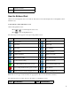
MODE DESCRIPTION Chase (default) Chase the LEDs to stay online. The LEDs represent the swath location relative to the vehicle. For example, if the vehicle moves offline to the left, the lit LEDs move right. Pull Center the LEDs to stay online. The LEDs represent the vehicle position relative to the swath. For example, if the vehicle moves offline to the left, the lit LEDs also move left. To change the LED mode, select Configuration / System / Guidance / LED Mode.
A positive timezone indicates a zone that is ahead of Greenwich, England. A negative timezone is behind. Driving on Large Fields At distances greater than 10 km (6.2 miles) from the original AB Line, the curvature of the Earth's surface can cause a reduction in GPS position accuracy. Consequently, the lightbar does not support more than 1024 swaths to the left and 1024 swaths to the right of the original AB Line.
To change when coverage logging is enabled: 1. In Advanced mode, select Configuration / System / Guidance / Coverage Logging. The Coverage Logging screen appears. 2. Select the appropriate setting and then press . Adding a Time Delay to Coverage Logging There may be a delay between the time when you start or stop drawing coverage onscreen and the time when the implement actually starts or stops coverage. For example, some spray valves can take 1.5 seconds to open or close.
Connecting a device to receive speed pulses To connect the lightbar to a spray controller: 1. Attach the R1 end of the radar cable to the P5 connector of the all−port cable (P/N 64045). 2. Attach the P2 end of the radar cable to the device requiring radar speed input. 3. If required, use a fly−lead to connect a spray switch to the P3 connector of the radar cable. Configuring the lightbar 1. Select Configuration / System / Radar Output: . 2. Configure the radar settings: ♦ Radar Enabled must be On.
For information on how to calibrate the unit, refer to the controller instruction manual. Note: To check the accuracy of your current settings, compare the speed value indicated on the lightbar guidance system with that on the spray controller. Recording Events The EZ−Guide 250 lightbar can record events for playback. Only use this feature if directed to by your support provider.
Advanced Mode GPS Corrections Configuring the GPS Corrections The term GPS corrections refers to the type of GPS signal that you receive. ITEM DESCRIPTION WAAS (Wide Area Augmentation System) WAAS corrections are an overlay to the normal GPS signal to improve accuracy. WAAS is available only in the United States of America, southern Canada, and the northern parts of Mexico. It is free to use.
2. Select the appropriate correction method and then press correction appears as the Source. 3. Press to select Next Screen and then press . . The GPS Source screen reappears. The Configuring WAAS/EGNOS To configure WAAS or EGNOS corrections, set each of the fields on the WAAS/EGNOS Settings screen: ITEM DESCRIPTION Correction Limit The time that the lightbar can run without receiving an updated GPS position, before it drops guidance. Satellite The correction satellite that the lightbar will use.
2. Adjust the value and then press . ITEM DESCRIPTION Minimum Elevation Elevation refers to the angle at which a satellite appears in the sky (higher is better). The Minimum Elevation setting is the minimum angle in the sky at which the lightbar will acknowledge satellites. If you are having trouble receiving corrections, lower this setting. Minimum SNR SNR (Signal to Noise Ratio) is a measure of the quality of a GPS signal. It is the ratio of useful information received to noise.
1. Set the lightbar port parameters. Tip − To be able to communicate, the parameters must match those of the device. 2. Select Next Screen and then press . The Message Selection screen appears. 3. Set the various message formats to On or Off, depending on whether they are required. 4. Select Next Screen and then press . 5. If you turned GGA on, then select the number of decimal places in the GGA message.
2. Select Configuration / System / GPS / GPS Setup. 3. Change the GPS Correction Source option to Ext. TSIP. 4. Select Continue and press . The Connecting to External Receiver screen appears. The lightbar connects to the TSIP receiver. The message Connection Established appears. 5. Press . The External DGPS Source screen appears, showing the available corrections on the reciever. 6. Select the appropriate correction source and then press . The wizard for that correction type appears.
When the lightbar receives OmniSTAR corrections from a TSIP−compatible receiver, the convergence time is reported differently. Using RTK corrected positions over TSIP When you use RTK positions from an external receiver, you can configure the network ID using the Network ID setting. On the main map screen, the Info tab shows a diagnostic called Link Quality . This describes the quality of the radio signal, and as a result the RTK signal.
Advanced Mode Data Management USB Drive Compatibility The EZ−Guide 250 lightbar saves data to and from a USB drive using a FAT file system. Caution − Multi−function devices, for example iPods or MP3 players, are not compatible with the lightbar. Do not reformat these devices to use the FAT file system, as this may delete their firmware and prevent them from operating correctly. The following drive is compatible with the lightbar: • Lexar Firefly 1 GB (P/N 64268−1G).
4. In the File system list, select FAT and then click Start. The USB drive is formatted with the FAT file system. Inserting a USB drive You can connect a USB drive to the USB port on the back of the lightbar: 1. Ensure that the lightbar is turned off. 2. Insert the USB drive into the USB port. 3. Turn on the lightbar. Note: To reduce any delay caused by the lightbar scanning the USB drive, keep the number of fields on the USB drive to a minimum.
1. Connect the USB drive. See USB Compatibility 2. Select Configuration / Data Management / Manage Fields / Get Fields from USB. 3. Do one of the following: ♦ Select the specific client, farm, and field to import. ♦ Select All to get all of the data in a category to the USB drive. Note: If you select All, you do not need to select the later options. 4. Select Import Files and then press . A warning message appears. 5. Press to continue. A screen with an hourglass appears.
3. Do one of the following for each of the Client, Farm, and Field options: ♦ Select the specific item to export. ♦ Select All to export all of the entries. 4. Select Export Files and then press . A warning screen appears. 5. Press to continue. A screen with an hourglass appears: The data is exported. Exporting large fields Tip: To export a large field, create a temporary new A+ field with no logging in it and then export the large field.
You can delete fields that you no longer require: 1. Select Configuration / Data Management / Manage Fields / Delete Selected Fields. 2. Select the Client, Farm, and Field to delete. You can also select to delete "All". 3. Select Delete Files and then press . A warning message appears. 4. Press to continue. A screen with an hourglass appears. The files are deleted. Deleting coverage logging You can delete coverage logging to free up space in the lightbar's internal memory: 1.
Event The event or application that is being applied on a particular "field" (see above). For example: − Spraying − Harvesting A client may have several farms, each of the farms may consist of several fields, and each field may be broken into a number of events. Default Field Names By default, the client, farm, field, and event names are automatically generated.
A message appears to warn that you will load the configuration over the current configuration. Press to proceed, or press the function button to exit without loading. Summary Report The lightbar can produce multi−page field summaries that contain a field map and report. These summaries are in RTF format and can be viewed on an office computer. The summary report is automatically created when you close the field. (A field is closed when you run the New Field Wizard).
To export the summary reports to the USB drive: 1. From the main guidance screen, press one or more times until you have selected . 2. Press . The Configuration screen appears. 3. From the Configuration screen, select Data Management / Summary Reports. The Summary Reports screen appears. 4. Ensure that a USB drive is inserted into the EZ−Guide 250 USB slot. 5. Select Send Summary Reports to USB and then press . The Send Summary to USB screen appears. 6.
To upgrade the lightbar firmware: 1. Download the self−extracting firmware file from www.EZ−Guide.com to your office computer. 2. Run the file and extract the contents to a temporary directory. 3. Copy the files from the temporary directory to the USB drive. 4. Insert the USB drive in the lightbar. 5. Turn on the lightbar. When the USB drive is detected, the lightbar runs the upgrade wizard. 6. Select the EZ−Guide firmware .img file and then press . The wizard installs the new firmware.
Mapping Introduction to Mapping The EZ−Guide 250 can map point, line and area features. Note: Mapping is disabled if you do not have good quality GPS. To enter mapping mode, select the icon and press . While in mapping mode you can map point, line and area features.
2. Press ICON to select the appropriate point feature icon. DESCRIPTION Map a rock point feature Map a weed point feature Map a tree point feature Map another generic point feature 3. Press . The point feature is mapped. Note: By default, the point feature is mapped at the antenna location. To change where a feature is mapped, see Recording Position . Mapping line features To map a line feature: 1. From mapping mode, select 2. Press to select and press . The line feature mapping icon appears. . 3.
Note: By default, the line feature is mapped at the antenna location. To change where a feature is mapped, see Recording Position . Mapping area features To map an area feature: 1. From mapping mode, select 2. Press ITEM and press . The area feature mapping icons appear. to select the appropriate area feature icon: DESCRIPTION Map a generic area feature. Map an exclusion zone. 3. Press . The lightbar begins recording the area feature. 4. Drive around the area feature. 5.
3. Press type. 4. Press to select Point, Line or Area and press to display the configuration screen for the feature to select Recording Position and press . The Recording Position screen appears. 5. Select the appropriate recording position and press . Warning Zones When a point, line, or area feature is mapped, you can configure a warning zone around the feature.
1. If the lightbar is not already in Advanced mode, change it to Advanced mode by selecting Configuration / User Mode. 2. Select Configuration / Mapping and then press . The Mapping menu appears. 3. Press to select Point , Line or Area and press configuration screen. 4. Press 5. Press 6. Press to display the Point, Line or Area feature . The Warning Distance screen appears. or to change the warning distance. . Note: Set the warning distance large enough to be safe for the entire vehicle length.
Deleting Features You can delete mapped features in two ways: • Manually delete the closest feature in the field • Delete all the features in a selected field. Manually deleting the closest feature To manually delete the closest feature: 1. Enter mapping mode. Select the icon and press . While features are mapped in the field, the Delete Features ( ) icon is shown. 2. Drive towards the feature you want to delete, until it is selected as the closest feature.
2. Press 3. Press to select Delete Features. . The Delete Features screen appears. 4. Select the Client, Farm and Field containing features you want to delete. 5. Select Delete Files and press . A confirmation screen appears. 6. Press . The mapped feature files for the select field are deleted.
Obtaining Information from the Lightbar The About the EZ−Guide Screen You can view the About the EZ−Guide screen in Easy or Advanced mode. To view the About the EZ−Guide screen, select Configuration / About the EZ−Guide. If you need to ask for support, have this information available. Information Tabs The lightbar has several information tabs that you can display over the screen. They can be viewed in Easy or Advanced mode. The tabs are see−through, so you can still see the vehicle underneath.
Status Screens The Status screens can be viewed in Advanced mode. To display the Status menu, select Configuration / Status. You can access seven screens from the Status menu: SCREEN DESCRIPTION GPS Status Displays information about your position and the current GPS signal strength. Satellite Status Displays information about the current GPS satellites. DGPS Status Displays which DGPS signal is selected. It is set at System / GPS / GPS Setup. System Status Displays information about the lightbar.