Version 4.
Table of Contents Introduction...............................................................................................................................................................1 Legal Notices.................................................................................................................................................1 About the EZ−Guide 500 System..................................................................................................................
Table of Contents Advanced Mode Guidance Selecting (Loading) a Field..........................................................................................................................47 Advanced Mode Additional Information..............................................................................................................52 Views...........................................................................................................................................................
Table of Contents Obtaining Information from the Lightbar...........................................................................................................90 The About the EZ−Guide Screen.................................................................................................................90 Information Tabs..........................................................................................................................................90 Status Screens.............................
Introduction Legal Notices (c) 2007−2009, Trimble Navigation Limited. All rights reserved. Trimble, AgGPS, EZ−Guide, and EZ−Steer are trademarks of Trimble Navigation Limited, registered in the United States and in other countries. Autopilot, Autoseed, FreeForm, OnPath, and SiteNet are trademarks of Trimble Navigation Limited. All other trademarks are the property of their respective owners.
• Help − the lightbar has built−in, context−sensitive help that lets you quickly find the information you need. • Quick reference card − the quick reference card describes the most common features of the lightbar. Technical Support If you have a problem and cannot find the information you need in the product documentation, contact your local reseller. Alternatively, go to the EZ−Guide website at http://www.ez−guide.com/.
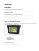
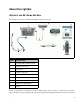
About the Lightbar What's in the EZ−Guide 500 Box The standard components of the EZ−Guide 500 system are shown below. ITEM DESCRIPTION 1 EZ−Guide 500 documentation CD 2 Quick Reference Card 3 RAM mount 4 Antenna mount plate 5 Power cable (P/N 62817) 6 Power connector cable (P/N 62818) 7 EZ−Guide 500 lightbar 8 Antenna cable (P/N 50449) 9 Antenna When you unpack the box, inspect all contents for visible damage, such as scratches or dents.
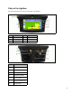
Parts of the Lightbar The following figures show the front and back of the lightbar.
How the Buttons Work On the front of the lightbar, there are six buttons. The buttons on the left and right sides of the lightbar work in different ways. Action buttons (on the right of the screen) On the main guidance screen: • Press • Press or to scroll through the action icons. to select the highlighted icon.
In setup screens, the icons match the buttons beside them. Function buttons (on the left) Beside each function button, there is an icon. When you press the function button, you select the feature that is shown on the icon.
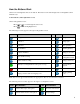
The EZ−Guide 500 lightbar has built−in help that explains how to use the current screen. To access the help, press the function button: Optional Accessories ITEM DESCRIPTION Antenna There are two antenna options for the EZ−Guide 500 lightbar: − Ag15 antenna for autonomous positions and free WAAS and EGNOS DGPS corrections − Z+ high−accuracy antenna for OmniSTAR XP/HP or RTK corrections Caution: Do not use the patch antenna from the EZ−Guide 250 lightbar with the EZ−Guide 500 lightbar.
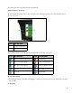
Note: Both fuses can be replaced by the user. Replacing the 30 A fuse 1. Locate the cigarette lighter plug holder on the end of the cable. 2. Unscrew the end cap where the spring−loaded pin protrudes. Be careful not to lose the pin after removing the end cap. 3. Remove the old fuse. 4. Insert the new fuse and then screw the end cap back onto the plug. Replacing the 10 A fuse 1. Open the cap on the fuse holder. 2. Pull out the old fuse. 3. Insert the new fuse. 4. Close the cap on the fuse holder.
Installation Step 1: Installing the Lightbar Mount 1. Select a place in the cab for the lightbar. There must be a mounting bar available for attaching the RAM mount. 2. Sit in the driver's seat and hold the lightbar in the place that you selected, make sure that you can access it comfortably from there. Step 2: Installing the Antenna Note: To minimize any interference to the GPS signal, make sure that the GPS antenna is at least 1 m (3 ft) from any other antenna (including a radio antenna).
ITEM DESCRIPTION 1 Antenna (P/N 60600−01 for DGPS or P/N 57200−00 for OmniSTAR/RTK) 2 Antenna cable (P/N 50449) 3 Remote keypad (optional − P/N 66030−00) 4 Power cable (P/N 60198 or P/N 62817) 5 Power connector cable (P/N 62818) 6 To power (cigarette lighter) 7 EZ−Guide 500 lightbar (reverse) 1. Connect the power cable to the power port on the back of the lightbar. Note: Ensure that the power cable points straight into the back of the lightbar − not at an angle. 2.
Step 4: Turning on the Lightbar To turn on the lightbar, plug the power cable into the cigarette lighter: • If the cigarette lighter is wired through the vehicle ignition, insert the key and turn on the vehicle ignition. The lightbar receives power and turns on. • If the cigarette lighter is not wired through the vehicle ignition, the lightbar receives power whenever the cable is plugged in.
4. Insert the wires with terminal connectors and the cable seals into the appropriate holes on the female WeatherPack connector: ♦ Ground wire − Connector hole B ♦ Switch wire − Connector hole C Caution: Ensure that you do not supply either wire with power. If necessary, use a relay to isolate the lightbar from the power source. 5. Plug the female connector into the male connector on the interface cable: Enabling the switch on the lightbar From the main guidance screen: 1.
4. Select System / Guidance. The Guidance screen appears: 5. Select Coverage Logging and then press . The Coverage Logging screen appears: 6. Press until you have selected Switch and then press . 7. In the Coverage Logging Input screen, select one of the two options: ITEM DESCRIPTION When the switch is closed, the two pins should be crossed and the coverage will be recorded. Active Low When the switch is open, the two pins will not be in contact and the coverage will not be recorded.
Getting Started Quick Start Wizard When you turn on the lightbar the Welcome to EZ−Guide 500 screen appears automatically: Press . The Quick Start Wizard appears. The wizard has several setup screens that enable you to configure important settings before you begin driving. During the Quick Start Wizard, you can press the function button to exit at any point. The system uses any settings you have entered; for any settings that you have not yet entered, the system uses the settings from last time.
1. Press 2. Press or to select the correct value. to enter the selection and proceed. You can select whether or not the Quick Start Wizard appears next time you turn on the lightbar. If you choose to hide the wizard at startup, the lightbar skips the wizard and starts on the main guidance screen. To alter these settings after startup, run the Quick Start Wizard from Configuration / Quick Start Wizard. Once you complete the Quick Start Wizard, the main guidance screen appears.
View Modes There are two views when you are driving in the field: PERSPECTIVE MAP VIEW PLAN MAP VIEW A 3D view of the field A bird's eye view of the field By default, the view switches from plan view to perspective view when you enter the field. You can change the view mode in Advanced mode. Panning On the EZ−Guide 500 lightbar, you can pan (move) the screen around to better see parts of the field, for example to check for skips in application coverage or the location of point, line and area features.
ITEM DESCRIPTION Zooms to the extents of the field. This includes the field boundary (if present), coverage logging and any mapped features. Zooms in Zooms out Note: To ensure all coverage logging is shown, turn off coverage logging before entering panning mode. Otherwise, the coverage polygon currently being recorded will not be shown in panning mode.
Changing the Backlight Brightness To change the strength of the screen backlight, select Configuration / Backlight. Changing the LED Brightness To adjust the brightness of the LEDs on the lightbar, select Configuration / LED Brightness. • In bright sunlight, increase the brightness to make the LEDs more obvious. • In darker conditions, for example driving at dusk, you can lower the brightness settings so the LEDs are less intense.
6. Select the appropriate correction source and then press . The wizard for that correction type appears. Note: When the lightbar is receiving GPS positions from the TSIP−compatible receiver, additional entries appear on the Info tab.
Easy Mode Guidance Introduction to Guidance The EZ−Guide 500 lightbar uses onscreen lines, either straight or curved, to guide you. These are called the guidance lines. The most simple form of guidance line is a straight AB Line. To create an AB Line, you define a start point (the A point) and an end point (the B point). Once you define the A and B points, a straight line is drawn between them. This is your master line.
The master line that you created, and that the swaths are based on. The A (start) and B (end) point on the master line. The first swath to the left of the master line. (The direction "left" is relative to the direction the master line was drawn, not the vehicle's current position). The current swath and tag are orange. Note: On a Pivot pattern, the swaths are numbered out from the center, not from the initial swath. The second line to the left of the master line.
ITEM DESCRIPTION 1 Offline distance 2 Guidance line 3 Vehicle position Guidance Patterns The EZ−Guide 500 lightbar has seven guidance patterns so you can create guidance to suit your field layout. Straight AB A Straight AB is the most simple form of line. Use a straight AB Line when you do not need to define headlands and you want to drive the field in parallel straight lines. To create a straight AB Line, define a start point (A) and an end point (B).
1. Drive to the start point of the master line. 2. Set the A point: a. Press or until you have selected the b. Press . The A point is set. 3. Drive to the other end of the line. 4. Ensure that the icon is selected and then press icon. . The master AB Line appears. 5. Turn left or right for the next swath. As you move toward the next swath, it appears on the screen and turns orange to show that it is selected. A+ Line An A+ line is also a straight line.
Mapping an A+ line 1. Drive to the start point of the master line. 2. Set the A point: a. Press or until you have selected the icon. b. Press . The A point is set. Because you have already set the line heading, your master AB Line appears on the screen. 3. Follow the AB Line for guidance down the first swath. 4. Turn left or right for the next swath. As you move toward the next swath, it appears on the screen and turns orange to show that it is selected.
PATTERN EXAMPLE There are two ways to define adaptive curves: • Set the A and B points • Set the A point and perform a U−turn onto the next swath (which is automatically detected) The method that you use depends on the Auto U−Turn detection setting. Changing the Auto U−Turn detection setting Note: To change the Auto U−turn detection, the lightbar must be in Advanced mode. 1. Select Configuration / System / Guidance. The Guidance screen appears. 2. Adjust the Auto U−Turn detection setting.
2. Set the A point: a. Press or until you have selected the icon. b. Press . The A point is set. 3. Drive the initial curve. 4. At the end of the first curve, perform a U−turn. The system detects the turn and generates the next swath. Adaptive curves with manually defined swaths 1. Drive to the start point of the curve. 2. Set the A point: a. Press or until you have selected the b. Press . The A point is set. 3. Drive the initial curve. 4. At the end of the first curve, select the icon.
Mapping a pivot Note: Always set the master line near the outer edge of the field. 1. Drive to the start point of the pivot. 2. Position one wheel of the vehicle in a pivot wheel rut, with the rear of the vehicle to the pivot arm. If the field is not a full circle pivot, face the rear of the vehicle to the edge of the field. 3. Set the A point: a. Press or until you have selected the icon. b. Press . The A point is set. 4. Drive around the field. Keep the vehicle wheel in the rut.
You can change two settings for the Headland pattern: • The number of circuits • The internal pattern (in Advanced mode only) Number of circuits When you create a headland, you need to specify the total number of circuits (including the master headland). This defines how wide the headland is. Note: No matter how many circuits you are creating, you only define the outside headland. The inner headlands circuits are copied from that original circuit.
• Drive the headland until you return to the start point. When you enter the circle around the start point, the headland completes automatically. • Drive part of the headland and then select . The headland completes with a straight line from the vehicle position back to the start point. Reselecting the headland When you use the headland pattern, you can see either the headland or the internal pattern, not both at once.
5. To complete the headland, do one of the following: ♦ Drive around the rest of the headland and then drive back into the start−point circle. When you drive into the start−point circle, the headland is defined. ♦ Select the icon and then press . The headland completes with a straight line from the vehicle position to the start point. The headland guidance line appears.
1. Set the lightbar to Advanced mode. 2. Select Configuration / System / Guidance / FreeForm Recording. 3. Select the appropriate setting. Recording a FreeForm curve It is necessary to record each curved pass, so the lightbar can create the next guidance line. 1. Set the FreeForm Recording option. 2. Drive to the start point of the FreeForm curve. 3. Begin logging your path: ♦ Select the icon and then press . ♦ If the FreeForm Recording mode is set to Coverage, select the icon.
the vehicle that shows your current guidance. You need to be creating a new guidance line: ITEM DESCRIPTION 1 Existing guidance line 2 New guidance line Getting guidance on straight segments When driving on straight AB Lines, you do not have to record your path as the guidance lines are generated automatically. The Next AB icon To switch from the current FreeForm guidance line to another, select the Next AB icon. The first time that you select the icon, guidance snaps to the next nearest curve.
To snap guidance to the straight line at the top of the screen, press the next AB icon again. Using FreeForm curves in spiral fields (round and round) If you are creating a spiral into the center of the field, drive the full circuit and then back onto the start of the FreeForm curve. Continue to record your guidance path as you spiral toward the center of the field.
3. Enter any additional pattern information (if necessary): a. Set the A+ heading (for A+ patterns only) b. Define the number of headland circuits (for headlands only) 4. Define the pattern on the field. Step 1. Entering the vehicle information 1. From the main guidance screen, select and then press : 2. Enter the implement width and then press . The Overlap/Skip screen appears. 3. Do one of the following: ♦ If you want your passes to overlap, press to enter an overlap distance.
1. On the A+ Heading screen, press or until the screen displays the required heading. Note: The default heading is the heading of the previous AB Line. 2. Press . The main guidance screen appears. Defining the number of headland circuits When you create a headland, you need to specify the number of circuits. This is the number of headland circuits that will be generated after you have driven the first headland circuit. 1. On the Headlands Circuits screen, press or of circuits. 2. Press .
4. Map the B point (if necessary). Note: For a headland, select the icon or drive back into the circle around the start point. 5. Turn and follow the guidance. Coverage Logging Coverage logging draws a solid block of color behind the vehicle to show the area that you have applied. When you pass over an area for the second time, the color of the covered area changes. This is useful for viewing any overlap.
The two status text items at the top of the screen show your current position relative to the pause position: ITEM DESCRIPTION Distance The vehicle's current distance from the pause position. Heading The vehicle's current direction relative to the pause position. For example: 0° = pointing directly toward the pause position 180° = pointing directly away from the pause position To pause guidance, select the icon and then press .
Advanced Mode Guidance Resetting Guidance Use the icon to create or load a field or line. To reset guidance: 1. Select the icon and press . The Finished With Field? screen appears. 2. Select one of the two options and then press : ♦ Yes − To map a new field (see Creating a New Field or Line ) or select an existing field (see Selecting a Field ). ♦ No − To map a new AB Line (see Adding an AB Line ) or select an existing AB Line in the current field (see Selecting an AB Line ).
4. Name the field (if you are creating a field). 5. Enter record keeping information. 6. Drive and define the guidance line. Step 1: Selecting the pattern type Note: If the pattern type and implement setup are already correct, just press 1. Press to select Pattern Type. 2. Press . The Pattern Type screen appears. . 3. Select which of the seven guidance patterns you want to base guidance on. For a description of the different field patterns, see Guidance Patterns.
Step 4: Naming the field When you create a new field in Advanced mode, the first Confirm Configuration screen displays the field name information. By default, the Client and Farm options show whatever you entered last time: To rename the field: 1. Press to select the Client option and then press . The Client screen appears. 2. Select one of the following: ♦ Create New − to enter a new name ♦ Any other entry − to use an exisitng name 3. Repeat Steps 1 and 2 for the Farm, Field, and Event. 4.
On this screen, you can add additional information to aid your record keeping: ITEM Operator EPA License Number Harvest Year Farm Location Vehicle Implement Application Method Soil Conditions Soil Type Temperature Humidity Wind Speed Wind Direction Wind Gust Speed Sky Conditions Crop Target Pests Applied Material Custom1 Custom2 Custom3 Custom4 DESCRIPTION The name of the vehicle operator. (USA) Your EPA license number for spreading restricted−use or state−restricted pesticides or herbicides.
Step 6: Driving and defining the guidance line Depending on the pattern type that you selected, one of the following icons is now available: • (start AB Line, A+, Identical Curve, Adaptive Curve, or Pivot) • (start Headland) • (not currently recording FreeForm curve) Drive to the start point and then select one of these icons to begin defining guidance. For more information about the various field patterns, see Guidance Patterns.
2. Press . The Pattern Type screen appears. 3. Select which of the seven guidance patterns you want to base guidance on. For a description of the different field patterns, see Guidance Patterns. Step 2: Setting up the implement (if necessary) To make optimal use of the EZ−Guide 500 system, correctly configure the implement that is attached to the vehicle. If the implement is offset and you do not configure it, there will be gaps and overlaps in your coverage. See Implement Setup.
Drive to the start point and then select one of these icons to begin defining guidance. For more information about the various field patterns, see Guidance Patterns. Implement Setup To make optimal use of the EZ−Guide 500 system, correctly configure the implement that is attached to the vehicle. If the implement is offset and you do not configure it, there will be gaps and overlaps in your coverage. From the Create New Field or Add AB Line screens: 1. Select Implement Setup and then press .
Overlap Set an overlap only if you want the implement to overlap the previous swath. Left/Right Offset If the implement is offset to either the left or the right, set an offset. Note: If you configure an implement offset, the guidance line will be centered on the middle of the implement and the vehicle will appear to be offline. Use the lightbar LEDs for guidance. If the implement protrudes to the left, set a left offset. If the implement protrudes to the right, set a right offset.
1. Select the AB Line 2. Set up the implement 3. Select the number of headland circuits (if necessary) Step 1. Selecting the AB Line 1. On the Create new or select old swath screen, choose Select AB Line. If there is only one guidance line in the current field, the main guidance line appears with the guidance line loaded. See Implement Setup. If there is more than one guidance line in the current field, the Select Stored AB Line screen appears and shows the guidance lines that are available to load. 2.
1. Press 2. Press or until you set the appropriate number of circuits. . The main guidance screen appears with the headland loaded. Selecting (Loading) a Field Note: You do not have to actively save a field. Fields are stored automatically. To load a field, do the following: 1. Select the field to load. 2. Select or create the event. 3. Select the line to load. 4. Set up the implement (if necessary). These steps are described below. Step 1.
2. Press . The FieldFinder map view appears. 3. Use the arrow keys on the left of the screen to select the field you want to load. 4. Press .The Choose an event screen appears. Selecting the Field name from a list You can select the field from a list of names, instead of a map. This can be useful if the lightbar is not receiving a GPS signal. To select a field from a list of names: 1. From the Create new field or select old field screen, select Select Stored Field .
2. Press . The Select Stored Field screen appears. 3. Select the client. a. Press to select Client and press . The Client screen appears. b. Press or until you select the desired Client name. c. Press . The Select Stored Field screen reappears. 4. Select the farm, using the same process as for client. 5. Select the field, using the same process as for client and farm. 6. Press to select Continue . 7. Press .The Choose an event screen appears.
Step 2: Selecting or creating the event 1. Press 2. Press or . until you select either New Event or Continue old event. If you selected New Event, you must enter a name for the new event. Note: If you want to create a new line in this field, load an existing line, select the icon and then create a new line. One of the following occurs: • If there is only one saved line, it is automatically selected. See Implement Setup. • If there is more than one saved line, the Select Stored AB Line screen appears.
Step 4: Setting up the implement To make optimal use of the EZ−Guide 500 system, correctly configure the implement that is attached to the vehicle. If the implement is offset and you do not configure it, there will be gaps and overlaps in your coverage. See Implement Setup. If you do not need to change the implement configuration, select Next Screen and then press .
Advanced Mode Additional Information Views There are two possible views when you are driving in the field in Advanced mode: Perspective map view Plan map view The view that is shown is controlled by the view mode: ITEM DESCRIPTION Auto Headlands (default) Shows the perspective map view on swaths and the plan map view in headlands. Auto Engage Shows the perspective map view when the EZ−Steer system is engaged and the plan map view when the system is disengaged.
To change to night mode, select Configuration / System / Display / Color Scheme and select Night Mode . Nudge Nudge a guidance line if you need to correct for: • GPS position drift when returning to the field for guidance, for example, after pausing or turning the unit off and on • GPS satellite constellation changes while driving in the field Each nudge moves the guidance line by the Nudge Increment value.
Note: The maximum Nudge Increment value is 30 cm (12"). To reset the nudge distance to 0, select Configuration / System / Guidance / Reset Nudge. Viewing the current amount of nudge There are two ways to view the current amount of nudge that has been applied: • The nudge value is displayed on the Tip/Message bar at the bottom of the screen while a nudge icon is highlighted • The first information tab shows the current nudge value. Press the function button.
line and save it. This can be useful for higher accuracy work, for example, to offset planting by half a swath width from one season to the next. To shift the lines: 1. Drive the vehicle along the line that you want to map the guidance to. Note: If you are driving at an angle of more than 10 degrees from the current swath, an error message appears. You must drive at almost the same angle as the guidance line. 2. Select the action icon. The Shift to Here screen appears: 3.
Setting the information tab transparency For a description of the information tabs, see Information tabs. The information tabs are transparent. To change the level of transparency, select Configuration / System / Display / Status Popup Transparency. 10 represents a solid black tab; 1 is barely visible. Setting the LED mode There are two LED modes: Mode Description Chase (default) Chase the LEDs to stay online. The LEDs represent the swath location relative to the vehicle.
US Central −6:00 −5:00 US Mountain −7:00 −6:00 US Pacific Time −8:00 −7:00 Australia East +10:00 +11:00 (except Queensland) Australia Central +9:30 +10:30 (except Northern Territory) Australia West +8:00 +9:00 A positive timezone indicates a zone that is ahead of Greenwich, England. A negative timezone is behind. Driving on Large Fields At distances greater than 10 km (6.
The lightbar displays a warning when you approach a tight turn. You may want to disengage the autosteer system and slow down to ensure that you turn smoothly and do not tangle the implement. To adjust the angle of turn that triggers that warning: 1. Select Configuration / System / Guidance / Tight turn alert threshold. 2. Select a value from 1 to 10. A low value triggers the warning even on gentle curves while a high value triggers the warning only on tight curves. The default value is 7.
Setting the Look Ahead Value The Look Ahead time predicts your future vehicle path to allow for reaction time and vehicle turn speed. For larger vehicles that take longer to turn, increase the time. Note: For 4WD articulated tractors, always set the Look Ahead time to 0 seconds. To adjust the Look Ahead value, select Configuration / System / Guidance / Look Ahead.
Setting up a controller On a Raven controller: 1. Make sure that the speed input is set to Speed Radar SP2. You usually choose the speed input setting when you first calibrate the unit; the choices given in most Raven controllers are SP1 or SP2. SP2 is the correct setting for Speed Radar inputs. For more information on how to check this setting, refer to your variable rate controller instruction manual. 2. Make sure that the speed calibration value is set correctly.
Advanced Mode GPS Corrections Configuring the GPS Corrections The term GPS corrections refers to the type of GPS signal that you receive. There are a number of different corrections, each of which has a different level of accuracy and different requirements. ITEM DESCRIPTION External Corrections Enables the lightbar to accept external RTCM corrections for DGPS positions. WAAS (Wide Area Augmentation System) WAAS corrections are an overlay to the normal GPS signal to improve accuracy.
2. Select the appropriate correction method and then press correction appears as the Source. 3. Press to select Next Screen and then press . . The GPS Source screen reappears. The Configuring WAAS/EGNOS To configure WAAS or EGNOS corrections, set each of the fields on the WAAS/EGNOS Settings screen: ITEM DESCRIPTION Correction Limit The time that the lightbar can run without receiving an updated GPS position, before it drops guidance. Satellite The correction satellite that the lightbar will use.
1. Adjust the OmniSTAR satellite information, if necessary. 2. Select Continue and then press . The OmniSTAR Satellite Settings screen appears: 3. Press the function button. The list of OmniSTAR contact telephone numbers appears. 4. Telephone OmniSTAR in your region and tell them your Unique User ID. This is displayed on the Subscription Setup screen. OmniSTAR will guide you through the process of activating your subscription. 5. If you are using OmniSTAR XP/HP, set the OmniSTAR engage accuracy.
7. Confirm the OmniSTAR settings. The OmniSTAR XP/HP or VBS corrections are now configured. Configuring RTK Note: If you want to use RTK corrections and output NMEA messages at the same time, you must connect the radio to the COM port on the lightbar and the NMEA device to the AUX port. Set the NMEA port to AUX in the NMEA output Port Parameters screen. Note: You should turn off coverage logging before changing RTK configuration settings.
2. Select Next Screen and then press . RTK corrections are configured. TrimbleRadio protocol 1. Set the Radio Network Number to match the network ID number of the base station. If the network IDs do not match, the radios will not communicate. 2. Select Next Screen and then press . RTK corrections are configured. Configuring the GPS Limits The GPS Limits screen enables you to adjust several of the GPS signal strength tolerances.
2. Adjust the value and then press . ITEM DESCRIPTION Minimum Elevation Elevation refers to the angle at which a satellite appears in the sky (higher is better). The Minimum Elevation setting is the minimum angle in the sky at which the lightbar will acknowledge satellites. Minimum SNR SNR (Signal to Noise Ratio) is a measure of the quality of a GPS signal. It is the ratio of useful information received to noise. A high SNR value is better.
To configure NMEA output, select Configuration / System / GPS / NMEA Output. 1. Set the NMEA output port option to the lightbar port that the NMEA device is connected to. 2. Set the lightbar port parameters. Tip − To be able to communicate, the parameters must match those of the device. 3. Select Next Screen and then press . The Message Selection screen appears. 4. Set the various message formats to On or Off, depending on whether they are required. 5. Select Next Screen and then press . 6.
ITEM 1 2 3 4 5 6 DESCRIPTION External interface cable (P/N 62749) To RTK radio RTK radio cable EZ−Guide 500 power cable (P/N 62817) Port expansion cable (P/N 62609) Connect COM 2 port connection cable (P/N 63076) and then NMEA device External Receiver Support The EZ−Guide 500 lightbar can recieve GPS positions from TSIP−compatible recievers. This enables you to use any of the correction types available on your receiver, including OmniSTAR, Beacon, and RTK.
To enable TSIP messages as the correction source: 1. Connect the receiver to the lightbar and then turn them on. 2. Select Configuration / System / GPS / GPS Setup. 3. Change the GPS Correction Source option to Ext. TSIP. 4. Select Continue and press . The Connecting to External Receiver screen appears. The lightbar connects to the TSIP receiver. The message Connection Established appears. 5. Press . The External DGPS Source screen appears, showing the available corrections on the reciever. 6.
Note : Do not manually disconnect the lightbar from the receiver. The lost signal causes the lightbar to perform an incorrect fast restart. When the lightbar receives OmniSTAR corrections from a TSIP−compatible receiver, the convergence time is reported differently. Using RTK corrected positions over TSIP When you use RTK positions from an external receiver, you can configure the network ID using the Network ID setting. On the main map screen, the Info tab shows a diagnostic called Link Quality .
Advanced Mode Data Management USB Drive Compatibility The EZ−Guide 500 lightbar saves data to and from a USB drive using a FAT file system. Caution − Multi−function devices, for example iPods or MP3 players, are not compatible with the lightbar. Do not reformat these devices to use the FAT file system, as this may delete their firmware and prevent them from operating correctly. The following drive is compatible with the lightbar: • Lexar Firefly 1 GB (P/N 64268−1G).
4. In the File system list, select FAT and then click Start. The USB drive is formatted with the FAT file system. Inserting a USB drive You can connect a USB drive to the USB port on the back of the lightbar: 1. Ensure that the lightbar is turned off. 2. Insert the USB drive into the USB port. 3. Turn on the lightbar. Note: To reduce any delay caused by the lightbar scanning the USB drive, keep the number of fields on the USB drive to a minimum.
1. Connect the USB drive. See USB Compatibility 2. Select Configuration / Data Management / Manage Fields / Get Fields from USB. 3. Do one of the following: ♦ Select the specific client, farm, and field to import. ♦ Select All to get all of the data in a category to the USB drive. Note: If you select All, you do not need to select the later options. 4. Select Import Files and then press . A warning message appears. 5. Press to continue. A screen with an hourglass appears.
3. Do one of the following for each of the Client, Farm, and Field options: ♦ Select the specific item to export. ♦ Select All to export all of the entries. 4. Select Export Files and then press . A warning screen appears. 5. Press to continue. A screen with an hourglass appears: The data is exported. Exporting large fields Tip: To export a large field, create a temporary new A+ field with no logging in it and then export the large field.
2. Do one of the following: ♦ Select the Client, Farm, and Field to delete. ♦ Select All from one of the categories to delete all the entries under that heading. 3. Select Delete Files and then press . A warning message appears. 4. Press to continue. A screen with an hourglass appears. The files are deleted. Deleting coverage logging You can delete coverage logging to free up space in the lightbar's internal memory: 1. From the main guidance screen, select the icon and then press .
− Spraying − Harvesting A client may have several farms, each of the farms may consist of several fields, and each field may be broken into a number of events. Default Field Names By default, the client, farm, field, and event names are automatically generated.
2. Select one of the following: ♦ Create New − Select Create New to enter a new name. ♦ Any other entry − Any other entries on the list are recent fields. 3. Repeat Steps 1 and 2 for the Farm, Field, and Event. 4. Press until you select Next Screen and then press . If the field does not already exist, it is now named. If the field already exists, the system displays a warning message. Go back and rename the field. Entering a new field name 1. Press to select Create New and then press .
Saving the system configuration 1. Select Configuration / Data Management / Save/Load Configurations / Save Current Configuration. 2. Select one of the following: ♦ Save to internal memory − Save the current configuration to the lightbar internal memory. ♦ Save to USB drive − Save the current configuration to a USB flash drive. ♦ An existing configuration − Saves the current configuration over the existing one. A warning message appears. Press to proceed, or press the function button to exit without saving.
continue. Note: A field must contain coverage for you to be able to generate a Summary Report. To manually create a field summary: 1. Open the appropriate field. 2. From the main guidance screen, press one or more times until you have selected . 3. Press . The Configuration screen appears. 4. From the Configuration screen, select Data Management / Summary Reports. The Summary Reports screen appears. 5. Select Create Summary Report Now and then press .
Data collected by the EZ−Guide 500 lightbar can be opened directly into the EZ−Office software that is available on the EZ−Office Software CD or from www.EZ−OfficeSoftware.com. Upgrading Firmware This section describes how to upgrade: • the EZ−Guide 500 lightbar firmware • the EZ−Boom controller firmware Upgrading the lightbar firmware Before you begin to update the firmware in the lightbar, check which firmware version is currently installed: 1. Select Configuration / About the EZ−Guide. 2.
Caution: Do not turn the lightbar off while the firmware is being updated. This could render the lightbar inoperable. 6. Select the EZ−Guide firmware .img file and then press 1.01. . The wizard installs the firmware version When the firmware is installed, the lightbar restarts. The lightbar detects the USB drive and the upgrade wizard runs again. The upgrade wizard now gives you three upgrade options: Caution: Do not turn the lightbar off while the firmware is being updated.
3. Copy the FW2 firmware upgrade file from the computer to the USB drive. 4. Ensure that the EZ−Boom 2010 system is correctly connected to the lightbar. 5. Insert the USB drive into the lightbar and then turn on the lightbar. The lightbar automatically detects the new EZ−Boom firmware and asks if you want to install it. Note: If the EZ−Boom controller is not detected, the lightbar will not show the firmware file.
Mapping Introduction to Mapping The EZ−Guide 500 can map point, line and area features. Note: Mapping is disabled if you do not have good quality GPS. To enter mapping mode, select the icon and press .
2. Press ICON to select the appropriate point feature icon. DESCRIPTION Map a rock point feature Map a weed point feature Map a tree point feature Map another generic point feature 3. Press . The point feature is mapped. Note: By default, the point feature is mapped at the antenna location. To change where a feature is mapped, see Recording Position . Mapping line features To map a line feature: 1. From mapping mode, select 2. Press to select and press . The line feature mapping icon appears. . 3.
Note: By default, the line feature is mapped at the antenna location. To change where a feature is mapped, see Recording Position . Mapping area features To map an area feature: 1. From mapping mode, select 2. Press and press . The area feature mapping icons appear. to select the appropriate area feature icon: ITEM DESCRIPTION Map a generic area feature. Map an exclusion zone. While the vehicle is in an exclusion zone, EZ−Boom stops spraying. 3. Press . The lightbar begins recording the area feature.
3. Press type. 4. Press to select Point, Line or Area and press to display the configuration screen for the feature to select Recording Position and press . The Recording Position screen appears. 5. Select the appropriate recording position and press . Warning Zones When a point, line, or area feature is mapped, you can configure a warning zone around the feature.
1. If the lightbar is not already in Advanced mode, change it to Advanced mode by selecting Configuration / User Mode. 2. Select Configuration / Mapping and then press . The Mapping menu appears. 3. Press to select Point , Line or Area and press configuration screen. 4. Press 5. Press 6. Press to display the Point, Line or Area feature . The Warning Distance screen appears. or to change the warning distance. . Note: Set the warning distance large enough to be safe for the entire vehicle length.
Deleting Features You can delete mapped features in two ways: • Manually delete the closest feature in the field • Delete all the features in a selected field. Manually deleting the closest feature To manually delete the closest feature: 1. Enter mapping mode. Select the icon and press . While features are mapped in the field, the Delete Features ( ) icon is shown. 2. Drive towards the feature you want to delete, until it is selected as the closest feature.
2. Press 3. Press to select Delete Features. . The Delete Features screen appears. 4. Select the Client, Farm and Field containing features you want to delete. 5. Select Delete Files and press . A confirmation screen appears. 6. Press . The mapped feature files for the select field are deleted.
Obtaining Information from the Lightbar The About the EZ−Guide Screen You can view the About the EZ−Guide screen in Easy or Advanced mode. To view the About the EZ−Guide screen, select Configuration / About the EZ−Guide. If you need to ask for support, have this information available. Information Tabs The lightbar has several information tabs that you can display over the screen. They can be viewed in Easy or Advanced mode. The tabs are see−through, so you can still see the vehicle underneath.
You can access seven screens from the Status menu: SCREEN DESCRIPTION GPS Status Displays information about your position and the current GPS signal strength. Satellite Status Displays information about the current GPS satellites. DGPS Status Displays which DGPS signal is selected. It is set at System / GPS / GPS Setup. Filter Status Displays the current GPS position filter being used. System Status Displays information about the lightbar.
The implement does not appear on the screen. The implement offset is too big for the current view. Point B does not appear. While you were defining a headland, you set A the point where you want to set the A point and then paused guidance the B point, resume the guidance mapping. mapping. The B point appears.
EZ−Boom 2010 System EZ−Boom Features When the EZ−Guide 500 system has firmware version 2.00 (or higher), it can be connected to the EZ−Boom 2010 automated application control system. This chapter describes features of the lightbar when an EZ−Boom 2010 system is connected.
• Additional status text items − ♦ If the EZ−Boom 2010 system is connected and the Rate switch is in either the Rate 1 or Rate 2 position, the lightbar shows two additional status text items: ◊ The intended target application rate (T:) is located at the bottom left of the main guidance screen. ◊ The actual current application rate (A:) is located at the bottom right of the main guidance screen.
METHOD DESCRIPTION Partial refill Increases the Current Volume value by the Partial Refill Quantity. This is useful if you add a specific amount of solution to the tank each time you refill it. Refill Resets the Current Volume value to the Capacity volume. EZ−Boom Flow Calibration When you perform the EZ−Boom 2010 system flow calibration: 1. Enter the Flow Meter Calibration number: 2.
4. Turn the Master switch back on. The system is now in full manual mode. This can be useful for spraying corners or to continue spraying if you lose GPS signal. To change back to automated mode, move the Rate switch to 1 or 2. Swath Control Menu Use the Swath Control menu to configure the following settings: ITEM DESCRIPTION Boom Control Enable or disable automated boom switching contol. Controls the amount of overlap allowed before a boom section is switched off.
Prescriptions Introduction to Prescriptions The EZ−Guide 500 lightbar can import variable rate prescription files in Shapefile format. The application rate information from the prescription attribute file (.dbf) is sent to EZ−Boom to control flow rates. Variable rate prescription functionality is only available after a password upgrade has been purchased. For more information on purchasing the variable rate prescription functionality, contact your local EZ−Guide 500 reseller.
Note: The EZ−Guide 500 will only detect prescription files located in the \AgGPS\Prescriptions\ folder on the USB drive. 2. Insert the USB drive into the EZ−Guide 500 lightbar and turn it on. Wait for the green USB icon to appear on the main map screen. 3. If the lightbar is not already in Advanced mode, change it to Advanced mode by selecting Configuration / User Mode. 4. To copy the prescriptions from the USB drive to the lightbar: a.
To load a prescription: 1. Press or to select the prescription to load. Note: To continue without loading a prescription, select None. 2. Press . The Prescription Parameters screen appears. 3. Press to configure the prescription setup: ITEM Rate Column Rate Units Scale Factor Rate Outside Polygon DESCRIPTION Column in the prescription .dbf file containing the rate information. Units that the application rate information is stored in. Applied to the rate information to scale the application.
2. Select No and then press . The Create New or Select Old Swath screen appears. 3. Press to choose Select AB Line and press . 4. Select the current AB Line and press . The Select Stored AB Line screen appears. Note: If there is only one AB Line in the current field, this step is done automatically. 5. Press to keep the current implement setup. The Available Prescriptions List screen appears.
6. Select the prescription file you want to load and press .